
ARC/Short Circuit
Interfacing
Safety
Technology/Terminology
Linear versus Switch Mode Power Supplies
Voltage Mode/Current Mode. Why a power supply can only regulate only one of these parameters at a time.
What is a “stack” type high voltage power supply?
What is a High Voltage (HV) Power Supply?
What is a resonant inverter?
What is a voltage multiplier?
What is an electrical corona?
What is Ball Soldering?
What is floating ground?
What is power control? When would it be used?
What is solid encapsulation?
What is the difference between a modular power supply and a rack supply?
What is the difference between voltage mode and current mode?
Why are corona rings/toroids/balls used on high voltage power supplies?
Why do I have to provide a current programming signal to the power supply?
Why is oil insulation used?
Usage/Application
Can I float your high voltage power supplies?
Can I get twice the current from your supply if I run it at half voltage?
Can I Operate a high voltage power supply designed for 220Vac, single phase from a 208Vac, three phase electrical service?
Can I Operate Your 220Vac Power Supplies at 230Vac?
Can I run your power supplies at maximum voltage? Maximum current? How much should I de-rate your supplies?
How should I ground your supply?
Positive polarity, negative polarity, reversible polarity; why is this important when I purchase a supply?
What are the bandwidth capabilities of the HVD Series of High Voltage Dividers?
What is power factor? What is the power factor of a switching power supply?
Why do I have to fill out a capacitor charging questionnaire if I’m going to use your power supply for capacitor charging?
Why is the fall time of your supplies load dependent?
| Title | Type | Size |
Download
|
|---|---|---|---|
|
pdf
|
182 KB
|
|
|
|
pdf
|
206 KB
|
|
Monoblock® Cooling
Monoblock® Long Term Storage
Monoblock® Maintenance
Monoblock® Minimum Settings
Monoblock® Mounting
Monoblock® Seasoning
Monoblock® Tube Life
AN-02: Common X-Ray Tube Failure Modes
Common X-Ray Tube Failure Modes
AN-02
Introduction
X-Ray tubes are a proven, cost effective way to produce X-radiation useful in the medical, inspection and scientific fields. For over 100 years X-Ray tubes have made advances owing to new applications, materials, processing equipment and design. Today two types of tubes dominate: rotating anode tubes used primarily for medical purposes from 25 kilovolts (kV) to 150 kV, and stationary anode tubes used in the inspection industry from 25 kV to over 400 kV with some in the million volt range. Stationary anode tubes typically operate at 1-20 milliamperes in nearly continuous duty and can be on for many hours at a time. Rotating anode tubes operate in excess of 1000 milliamperes but are used primarily in a pulsed mode of about 1 millisecond to 10 seconds.
In the production of X-Rays less than 1% of the energy produces useful X-rays while the remaining 99% is transformed into heat. This factor limits the useful life of the X-ray tube. Many scientific disciplines are required and must be controlled to produce a quality product. These include: thermodynamics, heat transfer, materials science, vacuum technology, high voltage, electronics, atomic/radiation disciplines, manufacturing processes, and many lesser but important technologies. The integration and control of the X-Ray tube and generator is critical to producing anticipated technical results and long tube life.
1. Normal Aging
a) Normal Filament Burn Out
b) Accelerated Filament Burn Out
c) Slow Leaks
d) Inactivity
e) Glass Crazing
f) Arcing
g) Target Micro-cracking
h) Accidental Damage
i) Bearings
2. Deficiencies in Manufacturing
a) Immediate Failures
i) Weed Out by Test
ii) Hold Period
iii) Improper Materials
iv) Process Failures
b) Latent Failures
i) Process Optimization
ii) Marginal/Poorly Understood Processes
iii) Failure Analysis/Untraceable Causes
3. Application Mismatch
a) Low kV/High mA Emission
b) Temperature/Life
4. Improper Drive by the Power Supply
a) Supply Impedance
b) DC/AC Filament
c) High Frequency
d) Rotational Speed/Brake
e) Filament Boost
f) Logic Circuits
g) Filament Limit/Filament Preheat Settings
5. Tube Enclosure Considerations
a) Dielectric (oil) Leak
b) Overheating
c) Ambient Temperatures
d) Housing Attitude
e) Cable/Ground Connections
f) Dielectric Expansion Requirements
g) Rating Discipline
1. Normal Aging.
X-Ray tubes age and have a limited life because the characteristics and materials used begin a gradual degradation and are consumed so that performance gradually decreases until they no longer perform satisfactory.
a. Normal Filament Burn Out: The electron beam in an X-Ray tube is supplied by a tungsten filament which has been used since the inception of electron tubes and also in incandescent light bulbs. Despite experimentation with other emitters: dispenser cathodes, Lanthanum and Cerium hexaboride, thorium and rhenium doped tungsten, pure tungsten has remained the best filament material. The filament is made from wire which is wound into a helix and inserted into a cup which acts as a focusing element to form the necessary rectangular electron beam. The helix serves to strengthen the filament and provides increased surface area to maximize electron emission.
Tungsten wire is readily available and processed into useable forms. The wire is relatively strong, rugged and keeps its shape when stresses such as vibration and shock are controlled. X-ray tube manufacturers stabilize and strengthen the filaments with a process called recrystallization. This changes the raw fibrous wire microstructure into one which the crystal structure has a length to diameter ratio in the range of 3 to 6. Recrystallization is accomplished by heating the wire very rapidly to about 2600 Celsius in a few seconds and holding it there for a very short time.
A common parameter for filaments is the filament life. When hot tungsten slowly evaporates from its surface, the higher the temperature the greater the evaporation rate. Ideally tungsten evaporates uniformly but in practice it begins to form hot spots at crystal grain boundaries which are visible as “notches”. Hot spots evaporate tungsten more readily and the wire thins more at these locations, ultimately burning open. The higher the filament temperature the more the tungsten grains grow with time and the quicker the notching progresses. Additionally if high inrush currents are allowed with a cold filament this accelerates burn out by overheating the thinned spots.
For filament life, a reduction of about 10% of the wire mass is considered to be the end of life. This represents a reduction of 5.13% in the wire diameter and the filament has attained about 98% of its life. (Tungsten Filament Life Under Constant-Current Heating, A. Wilson, Journal of Applied Physics, vol. 40 No. 4 Pg. 1956, 15 March 1969) (This reference also has a good picture of a notched filament run under direct current conditions and an unnotched wire run under alternating current conditions.) A 5 or 6% decrease in diameter is considered end of life by many manufacturers.
b. Accelerated Filament Burn Out: X-Ray tube characteristics are affected by several factors including: tube current, tube voltage, anode to cathode spacing, target angle and the focal spot size (electron beam size). The focal spot size is affected by: surface area of the wire, helix pitch (the number of turns per inch), helix diameter/length, proudness of the filament in its focus cup, and the shape of the cup itself. Only the anode to cathode high voltage and the filament current (temperature) determines the tube emission. The emission is governed by the Richardson-Duschman equation which is very dependent on filament temperature; the higher the temperature, the more emission.
The filament in a tube runs hotter when more tube current is demanded from the tube at a fixed voltage or when more tube current is demanded but the tube runs at a lower voltage. For example two cases are compared for a stationary anode tube. First: a tube operating at 160 kV @ 1 milliampere (mA), compared to 5 mA. In this tube the filament is calculated to run about 2086 degrees Kelvin, compared to 2260 degrees Kelvin at 5 mA. The 174 degree increase produces an evaporation rate 21 times as much for the 5 milliampere operation compared to 1 mA. (“The Rates of Evaporation and the Vapor Pressure of Tungsten…”, Jones and Mackay, Physical Review, Vol. XX No. 2, August 1927.) Second, for the same tube operated at 40 kV @ 5 mA compared to 160 kV and 1 mA the temperatures are 2300 K and 2086 K respectively which reduces life by a factor of about 43 times. Interestingly, a relatively small decrease in life is experienced with a low tube current when the tube voltage is reduced; for example 160 kV vs. 40 kV, both for 1 mA, only reduces the life by a factor of 1.3 and 160kV vs 40kV both at 5 mA reduces by 2.1 times.
In summary:
160 kV@5 mA vs. 160 kV@1 mA 21 times less filament life
40 kV@5 mA vs. 160 kV@1 mA 43 times less filament life
40 kV@1 mA vs. 160 kV@1 mA 1.3 times less filament life
40 kV@5 mA vs. 160 kV@5 mA 2.1 times less filament life
This shows that tube current increases (produced by filament temperature increases) are much more important than tube voltage changes. Individual tube types as well as individual tubes of a single type will vary from these examples.
Filament failures due to burn-out are caused by high operating temperatures; the higher the temperature, the sooner the filament burns open. Tungsten evaporates from the filament surface but in a non-uniform way, so hot spots are formed which evaporate more rapidly. Hot spots occur at tungsten crystal faces which evaporate preferentially at different crystal surfaces. The higher the temperature of the filament and the longer it operates there, the larger the crystals grow. Long life is achieved by having the crystals long and narrow along the axis of the wire and keeping the temperature as low as possible.
c. Slow Leaks: X-Ray tubes require a high vacuum to function. Glass-to-metal seals and metallic brazed joints which are suitable to begin with, start to fatigue and sometimes begin to allow minute amounts of gas to enter, gradually increasing the gas pressure. Tube performance begins to suffer due to materials evaporation and high voltage arc-over which can be caused by higher gas pressure.
d. Inactivity: Lack of operation allows gases within the tube vacuum to build and migrate along surfaces. When the filament is energized and high voltage is applied arc-over can occur especially at higher operating voltages. Most manufacturers recommend a warm-up procedure depending on the inactive time period. Necessarily this is a one-size-fits-most procedure but a single procedure may not fit all. For some cases, additional extended operation including higher power or voltage operation called seasoning, is necessary and helps the tube operation. This may not work satisfactorily or not at all and the tube must be replaced.
 e. Glass Crazing: Most tubes are manufactured with glass as the vacuum wall vessel but the glass also performs the task of insulating the tube electrodes (cathode, anode and ground) from leakage currents and arc-over. With time and depending on use factors, metal (tungsten) from the anode and filament begins to evaporate onto the glass surfaces causing eventual arc-over and tube failure.
The arcing disturbs the evaporated material and can cause glass insulators to become etched. This condition is often referred to as “crazing” or “etching”.
Various methods are used to mitigate the effects of the evaporation including: sand blasting the glass (which increases the insulating path), using a hooded anode on stationary anode tubes (a hood or shroud reduces target evaporations onto the glass), metal center vacuum walls (which reduce filament evaporation onto the glass in rotating anode tubes and some stationary anode tubes), and the use of ceramics. These techniques do not eliminate metal evaporation but greatly reduce its deposition onto the glass and ceramic insulating surfaces thus postponing the arc-over tendency. The techniques can produce other undesirable effects, for example sandblasting glass can lead to glass particle release which causes arc over.
 f. Arcing: Arcing is a common problem in all high voltage systems. Some causes have been mentioned above: high gas levels in the vacuum, evaporation of conducting metal on insulator surfaces, and crazing or etching of insulators which in turn produce higher gas pressure or degrade the insulators ability to hold off the high voltage. Other causes such as small insulator or metal particles which are freed by operation or can be generated within the tube produce gas and conductive films on insulators. These particles can
cause small but focused electron beams which trigger arcs.
g. Target Micro-cracking: When power is supplied to the tube, an electron beam strikes the target and the temperature under this beam rises rapidly. For stationary anode tubes the power and temperature is relatively low and equilibrium temperature is reached within fractions of a minute. The tungsten target surface can easily reach melting temperature of tungsten (3400 degrees Celsius) but is limited to about 400 degrees Celsius (750 Fahrenheit) so the tungsten disc will not detach from its copper base. The temperature rise at the target surface causes stresses which can result in minute cracking at the target surface. Over time and with on/off cycling these cracks grow and some of the electrons in the beam fall into these cracks so the resulting X-radiation is altered. Tungsten absorbs some of the radiation from the cracks and the radiation intensity is reduced and the energy of the X-Rays becomes harder (having higher energy rays). Running tubes at lower power and lesser target angle) also reduces this tendency.
For rotating anode tubes whose power capability can be up to 1000 times greater than a stationary anode, target micro-cracking is much more severe and its effects are therefore greater. Temperatures of the target focal spot in a rotating anode tube can reach 2800 degrees Celsius (over 5000 Fahrenheit). The reduced radiation vs the number of exposures is often referred to as “radiation fall-off”. Micro-cracking is reduced by using the lowest necessary power, the largest possible focal spot and longer exposures at reduced power rather than shorter exposures at higher power. Such criteria are also applicable to stationary anode tubes. Micro-cracking reduces heat transfer which increases the temperature of the focal spot which increases tungsten target evaporation onto the glass.
h. Accidental Damage: While not a high failure cause, accidental damage can be caused by not following recommended protocols during installation and operation. Misunderstanding, unfamiliarity, and assumptions can cause accidental damage. The carpenter adage applies: measure once, cut twice; measure twice, cut once. For X-Ray tubes, check and double check.
i. Bearings: Rotating anode tubes bearing failure can be problematic. All mechanical systems wear out and stop working so the trick is to achieve longevity. High temperature and high speed will reduce bearing life the most. With operation, the lubricant (which is usually silver or lead metal) wears off of the ball and race surfaces leaving steel-to-steel contact which leads to binding or jamming. With conservative use bearings usually outlast other failure mechanisms. Radiation requirements and operation should be carefully reviewed in detail when choosing a rotating anode over a stationary tube.
2. Deficiencies in manufacturing.
a. Immediate Failures: No matter how hard a manufacturer tries, not all tubes are made exactly alike. Small differences exist, but the manufacturer needs to make sure such differences do not impact the tube operation.
i. Weed Out by Test: After a tube is produced and processed it is subjected to a battery of tests to complete final processing but more importantly to make sure that it meets the performance standards established for that model. The tube is subjected to quality testing. The primary testing is the high voltage stability. Each tube is subjected to high voltages typically in excess of 15% or more over its maximum operating voltage while operating at maximum power capability. Such processing removes gasses and particles and seasons virgin surfaces to operate at high voltages. The tube is then subjected to a performance test
to check its high voltage stability such that no or limited arcs occur over a specified time frame when operating at maximum rated voltage.
Cathode emission, filament volt ampere characteristics, focal spot size, thermal loading and other pertinent characteristics are tested and measured. For rotating anode tubes additional tests such as noise, vibration, coast time and others are performed to assess the rotor and bearing performance. Tubes not meeting specifications are rejected/scrapped but analyzed to find offending causes so corrections can be made to the manufacturing process.
ii. Hold Period: Sometimes despite satisfactory testing if tubes are held for 2-4 weeks they do not perform satisfactorily especially under high voltage conditions. The change in performance is usually caused by tiny vacuum leaks which cannot be detected by normal means but produce gases which do not allow good (high voltage) performance. Normal thermal cycling can induce leaks or voids open up and introduce deleterious gasses. Such degradation of performance is rare but occurs and in some instances longer idle or normal inventory rotation times reveal additional failures.
iii. Improper Materials: Modern materials like: oxygen free copper, controlled expansion cobalt alloys, rhenium infused tungsten, high hot strength alloys, vacuum grade graphite, high temperature brazes, as well as ceramics and technical glasses have vastly improved tube performance. Because of such improvements a high level of quality assurance is necessary to guarantee these and other material quality. Testing and certificates of compliance are often used to insure supplier quality. Despite these efforts materials not up to standard can creep into the manufacturing process. A good example is oxygen free copper bar which if extruded can contain stringers which cause vacuum leaks. The more costly forged plate and bar must be used. Usually these deficiencies are caught in-house and are not seen by the customer.
iv. Process Failures: New processes such as: vacuum remelted metals, turbo-molecular vacuum pumps, high temperature vacuum processing, high temperature hydrogen gas firing, vacuum brazing and electro polishing also provide improved X-ray tube performance. Automation has helped insure more consistent product. However if these processes/equipment utilized become faulty or the control is lost, a well-tuned process can easily fail and marginal or reject tubes can result.
b. Latent Failures: Latent or unpredictable failures which occur in time are often unforeseen and sometimes may not be attributable to a known cause.
i. Process Optimization: Many processes used on tubes and their parts have evolved over many years and through practical experiences. Unless there is very clear contrary evidence manufacturers are reluctant to change a process for fear of unknown consequences. For example an anode with a graphite disc brazed to its back for a rotating anode tube must be outgasses prior to assembly. If the temperature is too high, damage in the braze and its
interface could occur, but if too low and adequate outgassing might be compromised. In a stationary anode, high temperature on the anode helps outgassing, but how high and for how long can the temperature be before (hidden) damage occurs? Many processes fall into this category, such as: outgassing, vacuum pumping, and seasoning. Being too conservative risks unsatisfactory performance, being too aggressive risks damage. It’s difficult to find a suitable compromise and once a process works it is often best to leave it alone.
ii. Marginal or Poorly Understood Processes: Some failures are caused by effects that are not well known or for which side effects of various processes are not known. Why does dielectric oil sometimes become dark and have foreign material, yet the tube operates OK? Other systems exhibit arcing yet the tube and cooling oil and surroundings look and test OK. The lubrication on the ball bearings in a rotating anode is a good example of not thoroughly understanding a process. The lubricant, usually lead or silver, is plated by chemical or physical evaporation methods and is blotchy in nature and not so uniform. Some run-in of the tubes is required to distribute the lubricant more uniformly. The average thickness is important also; too thin and bearing life is compromised, too thick and the tubes run rough and often jamb. Historical results and trial and error guides the process, but physical reasons are not well understood.
iii. Failure Analysis/Untraceable Causes: Failure analysis can reveal the cause of a failure and is an important process used by manufacturers to find latent and immediate failures. Sometimes the problem is obvious, other times a lot of analysis and testing is involved to uncover a root cause. Any person involved with failure analysis knows that despite a strong effort, many times it is not possible to find a root cause. Either the failure destroys definitive evidence, or the disassembly during analysis removes the evidence. Sometimes not enough evidence is found to make a definite conclusion. The best that can often be done is to extrapolate to a cause.
 A common failure for relatively long lived tubes is arcing. The most common proven causes of arcing are: high residual gas pressure, degradation of insulators and spurious electron emission (commonly called “field emission”). The first two subjects were touched on earlier. For field emission microscopic particles (both metallic conductors and non-metallic insulators) can cause small electrical currents typically in the nanoampere range which are emitted simply due to very high electrical fields. These minute currents which emanate in a beam form can under certain conditions charge insulators which then discharge thereby inducing an arc. The charging can also cause failure of the insulator in the form of a puncture which is a minute hole in the insulator causing loss of vacuum. Alternately particles can detach, accelerate thus pick up high energy in the electric field, and burst upon impact inducing an arc. The impact often causes secondary damage in the form of impact debris which in turn causes more field emission.
Manufacturers stress cleanliness in an effort to reduce particulates, usually assembling tubes in clean rooms and utilizing various processes such as ultrasonic cleaning or electropolishing to remove particles. Despite such efforts minute particulates still enter the tube. To mitigate particulates, every new tube is “seasoned” or exposed to high voltage operation up to about 25% of its maximum operating voltage in order to burn off or remove particulates to inactive parts of the tube. Seasoning a tube under cold conditions does little good so the tube must be operated through a particular thermal protocol of which many that are possible. The schedules for such seasoning comprise considerable experimentation and evaluation but are yet not always perfect. It is extremely difficult to get a tube which never arcs.
3. Application mismatch.
Early mammography is a good example of initial tube mismatch when a standard diagnostic tube was used to produce mammograms. The resulting diagnosis was rather poor and radiation burns often resulted. Over several years, it was learned that molybdenum radiation, at voltages of about 30 kV with very small focal spots designed into tubes which especially fitted the anatomy was very effective in providing early diagnosis of breast cancer. New tubes were designed to meet these requirements and today they are the gold standard for essential early detection.
a. Low kV/High mA Emission: A common mismatch can occur when a tube designed for high voltage use is used at lower voltages (typically one half or less of maximum), the filament has to be run at higher current to overcome the limited emission. In a particular rotating anode tube operated at 125 kV and 300 mA when decreasing to 50 kV and 300 mA the filament must be operated at 16 % more power to overcome the lower tube voltage. Since the filament cools by radiation with temperature proportional to the 4th power (T⁴), a 16% increase means only a 3.8% increase in filament temperature. While this seems small the tungsten is evaporating at about three times the rate at the higher power resulting in three times less filament life in this case. If the tube is operated at higher tube current (>300 mA in this case) at 50 kV, the filament current must be increased and even lower filament life results. Often such a mismatch must be accepted because a manufacturer is reductant to produce a special design especially if sales will be limited.
b. Temperature/Life: A basic rule for X-Ray tubes is that temperature is the enemy. The more power applied, the shorter the tube life. However without adequate power there may not be enough X-radiation intensity to get the job done. Filament evaporation causing unwanted metallic deposits will eventually lead to insulator arc over. Operating the target at higher temperature will not only eventually cause target evaporation, but the radiation quality in terms of energy distribution and intensity will begin to change and be reduced due to micro-cracking.
Thermomechanical stresses are present during tube operation. The glass to metal seals are stressed when heated and the more heat the higher the temperature leading to increased stress. Ultimately minute particles can break off or the glass forms fine cracks which are increased by radiation passage. Mechanical fatigue is always present due to thermally cycling and the more the cycling the quicker fatigue develops. Higher power causes higher temperature which accelerates fatigue. Operating the X-Ray tube at the lowest useable power extends life.
4. Improper drive by the Power Supply.
In an X-Ray source, the power supply provides all the necessary power to operate the tube including the filament and often the rotor supply for a rotating anode tube. Additionally the supply contains the logic and interlocks used by the system. Thus the supply is an integral part of the X-Ray source and both act in concert.
a. Supply Impedance: One of the most critical characteristics of the supply is its impedance. For stationary anode tubes, which operate at a few hundred watts, the impedance can be high meaning it contains a lot of resistance so in case of an arc damage to the tube and sensitive electronics is minimized. Arcing is usually extinguished when the voltage supporting the arc is reduced. When the current in an arc passes through the high voltage resistance, the voltage across the resistance increases thereby reducing the voltage on the tube and other parts of the high voltage circuitry. If the gas pressure in the tube gets so high as to sustain an arc the impedance also protects the supply and associated electronics. Nothing can be done to a tube to improve its performance when its gas level becomes too high.
Unfortunately high impedance also means that if arcing starts due to a particle or field emission or light evaporation, there is often not enough energy stored to clear-up or evaporate the cause and arcing may continue.
A rotating anode tube operates under much higher power conditions sometimes over 100 kilowatts or almost 1000 times a stationary anode. Here the supply cannot have high impedance otherwise it would not support the required power. In these cases, it is often necessary to limit the stored energy to typically less than 10 joules. High voltage cables and voltage multiplier capacitors will store such energy and damage to the tube in an arc can result. Ten joules is not a fixed value, only a guide as some tubes operate satisfactorily with more energy stored and others won’t operate with less energy. The capacitance becomes more troublesome at higher voltages as the energy is proportional to the voltage squared.
b. DC/AC Filament: Typically filaments are operated under alternating voltage/current conditions. There are three basic reasons. First it was historically easier to control and supply alternating currents (AC) and secondly there tends to be grain growth when direct currents (DC) are used causing brittle fragile filaments to form over time and burn open sooner. Lastly but less important is that under DC conditions at one end of the filament a small fixed potential will exist equal to the filament operating potential which can distort the focal spot by biasing it slightly with respect to the focusing cup. The effect is more pronounced with smaller focal spots and high emission conditions. With AC such bias alternates between both ends of the filament and so washes out.
For filaments heated by direct current, a phenomena of notching occurs especially for thin filaments. In this case some tungsten ions form from the evaporated tungsten atoms and are attracted toward the negative end of the filament and deposit themselves forming a series of “notches”. These notches are thinner than other sections of the filament and lead to hotspots with accompanying greater evaporation and ultimately burn-out. Filament life reduction of two to ten times is reported by operating with DC rather than AC. Modern power supplies that use DC filaments derive this from high frequency converter. Under these conditions, a low amplitude high frequency ripple in the order of 10s of kHz is present on the filament signal that minimizes the notching effects.
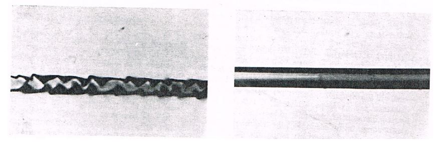
c. High Frequency: The glass-to-metal seals in a tube are made from Kovar or similar alloy consisting of iron, nickel and cobalt all of which are highly magnetic. The seals include the feedthroughs which carry the filament current. Under high frequency the magnetic materials are subject to magnetic hysteresis, eddy currents and the skin effect which sap the energy from the current flow. This phenomena requires that the supply deliver more power than compared to non-magnetic materials in order to overcome the loss. The higher the frequency the more the losses. The loss of power would heat the feedthroughs and the mechanical stressing effect in the seals is not well understood. Currently frequencies of up to 40 kHz are employed. For the cathode and anode, high frequency, high voltage supplies are employed, but these are rectified to DC.
d. Rotation Speed/Brake: For rotating tubes, bearing life as well as filament evaporation is a major consideration for tube life. When as exposure is called for, stator power is applied so the tube anode comes up to a rotation speed (revolutions per minute). Such minimal speed is specified by the manufacturer and the synchronized speed has historically four values based on the frequency of the commercial power; for 60 Hertz, the maximum speed is 3600 rpm or at triple speed 10800, for 50 Hertz power, 3000 rpm and 9000 for triple speed. These speeds are usually called “low” or “high” speed for normal singular frequency or triple frequency respectively. In practice the rotor can never quite reach this speed because friction in the bearings and less than complete magnetic coupling between the stator and rotor reduce the speed. In fact, the stator/rotor system is only about 10% efficient compared to commercial motors which are usually over 90%. For these reasons manufacturers generally specify a minimum speed typically 3000, 9500, 2800 and 8500 or values similar to allow for slip from the synchronous speed.
When an exposure is initiated, the stator power is applied for a specified amount of time to reach the minimum speed and depends on: the moment of inertia of the anode, (very roughly proportional to the heat storage capacity), the voltage applied to the stator, and the frequency of the applied voltage (high or low speed). Typically this rotor “boost” time is 1.5 to 6 or more seconds. After the boost is applied, the stator goes into the “run” mode where a reduced voltage (typically 80 to 100 volts) is continuously applied to maintain the minimum speed. Often it is left to the installer to adjust the boost time to meet the minimum speed and that can become a practical problem to implement. Reed tachometers and synchronous strobe lights can measure the rotational speed. The thermal state of the anode must be considered; a hot anode will come to a lesser speed than a cold anode due to increased friction and decreased magnetic coupling. Once the exposure is made the rotor speed is reduced or braked by applying voltage to only one winding of the stator.
Braking is done to quickly reduce bearing rotation but equally important to pass through the rotor resonance quickly. All rotors have a natural resonance frequency and at this point the rotor/anode can vibrate noticeably. To get through this resonance speed quickly and minimize any damaging effect, the brake voltage is applied. Typical resonance frequencies are about 4000 to 5000 rpm (65-80 Hz.), it is especially important to brake after high speed operation. Considering the usual shorter filament boost and longer rotor speed time it can be seen that the X-ray system sequence of events is: call for exposure, apply stator boost, apply filament boost, apply exposure high voltage pulse, reduce filament to idle, break anode speed. Modern power supplies have adjustment to all of these time sequences.
e. Filament Boost: When an X-ray tube is not producing X-rays (i.e. there is no high voltage applied to the cathode and anode) its filament is in the so called idle (or preheat) mode. It has current running through it but it is below the emission point where tube current would be drawn. Whenever an exposure is required the filament current is “boosted” to a predetermined current which allows a particular tube current to flow when high voltage is applied to the tube. When X-rays are no longer needed, the high voltage is switched off and the filament is returned to its idle current.
Typical filament boost times range from about one half to one second. This technique is especially important for a rotating anode tube where the tube currents are high and filament life is saved by operating it only when X-rays are needed. The filament idle current is chosen so that evaporation from the filament is a very small fraction of the filament current necessary for high emission thus minimizing evaporation at idle. If the tube current is sufficiently low, some stationary anode tubes are not boosted at all and the filament might be brought from a no power condition. Continuously pulsed systems can present a problem with evaporation because if the pulse repetition rate is high, there is not enough time between pulses to boost the filament before another pulse comes. Normally in these cases the filament is then run in the boost mode until all the pulsing is finished. Modern power supplies all adjustment to all of these time sequences.
f. Logic Circuits: As can be seen from the forgoing description, the logic sequencing and their performance is critically important. Add other systems such as interlocks, imaging sequencing, radiographic object requirements, and other system requirements it can be seen that functioning and reliability of the logic
systems is imperative if nothing is to go wrong. Sometimes tube arcing can cause transients initiated by current surges or high voltage interruption to produce circuit failures to the logic. Modern power supplies have isolated logic circuits that protect the sensitive electronics from transients under normal operation and arcing.
g. Filament Limit/Filament Preheat Settings: One of the most critical settings is the Filament Limit adjustment. The Filament Limit set point limits that maximum output current of the filament power supply to protect the filament of the X-Ray tube. This setting will make it impossible for the X-Ray generator to exceed this value under any circumstance. It should be set at or below the X-Ray tube manufacturer’s specification.
When setting the Filament Limit below the maximum X-Ray tube specification, the Filament Limit should be 10-15% higher than the filament current required to achieve the maximum programmed emission current (mA) at the lowest kV setting to be used. Remember, filament maximum values are different than the REQUIRED values for emission. Setting 10-15% over the needed emission current values provides headroom as well as better trainset response characteristics.
Always keep the Filament Limit level at or below the manufacturers recommended maximum filament current specification. The Filament Standby current (referred to as Filament Preheat on some product lines) is the idle current supplied to the X-Ray tube filament during X-Ray Standby (HV OFF/X-Ray disabled) conditions.
The Filament Preheat set point is typically around 1 amp to 2 amps, but the X-Ray tube manufacturer should be consulted. A good guideline to consider is the maximum Filament Preheat level should be limited to 50% of the Filament Limit specification. It is perfectly fine to set standby current to zero if fast emission current ramping is not required.
5. Tube Enclosure (Housing) considerations.
The X-ray tube must be enclosed in a suitable container in order to: prevent X-rays from emanating in all directions, provide suitable high voltage insulation and allow cooling of the tube/system. For a stand-alone X-ray tube the container is referred to as the housing, tube assembly or radiation source, and for a system in which the power supply is combined with the tube it is usually called a Monoblock® (Spellman registered trademark).
a. Dielectric (Oil) Leak: The dielectric, usually oxidization inhibited transformer oil, must provide high voltage insulation to prevent arcing from all high voltage surfaces. If oil leaks develop that usually means air also leaks in to the housing and if the air enters the high voltage field area it will cause an arc-over. If arcing continues, carbon from disintegration of the oil will begin to coat surfaces and they cannot be restored. Oil seals are often made by “O” rings and buna N rubber is suitable for the inhibited oil. Some materials such as neoprene are not suitable as they swell in this oil. Normal recommendations from the O ring manufacturers for compression percentages are about 5-10% and do not apply. About 25% compression is actually used as the O rings under typical high housing temperatures take a set and loose resilience and may begin to seep.
The oil used contains absorbed gasses which must be removed by vacuum treating to prevent their release in the housing. Such treating increases the dielectric strength as measured in units of volts per distance. Typical values are in excess of 30 kilovolts per inch. An important consideration is the materials used inside the housing, usually plastic insulators. These can leach plasticizers or other chemicals which can dissolve in the oil and degrade the dielectric strength. Temperature enhances the leaching. Care must be exercised to test materials used in the housing, even for new manufacturing lots of these parts.
b. Overheating: Overheating can cause acing not only in the tube but in the housing. Many systems have a heat exchanger which utilizes a fan and sometimes a pump to circulate the oil. It is imperative that these exchangers be kept clean. Dust is the major culprit and will inhibit both natural air convection and forced (fan) air convection. The result is that the housing becomes overheated, a maintenance schedule should be established.
c. Ambient Temperatures: Ambient temperatures need to be adhered to as specified by the manufacturer. A typical ambient is 25 or 30 Celsius, and under high load conditions, the housing can rise to 75 or 80 Celsius, a typical limit. Thus the temperature increase can be about 50 degrees and if the ambient is higher than specified, this temperature rise will be added to the ambient so that over temperature results. Enclosures, often used in test and to stop radiation leakage can cause ambient temperatures to rise above recommendations. Also it is not uncommon to find plastic or cloth covers used to “protect” the equipment, but these only frustrate the convection air flow and can easily lead to overheating.
d. Housing Attitude: A tube housing, with or without a heat exchanger can become hot on the top part and not on the bottom. This is because the dielectric cooling oil forms strong convection currents which rise like the smoke from a cigarette and carry heat to the top of the housing. Care must be exercised to insure the best housing attitude for operation. Often thermocouples can guide and reveal hot areas, but good thermal contact is necessary for accurate measurements.
e. Cable/Ground Connections: Although it seems obvious, good electrical connections are a necessity. Grounding especially as well as other connections such as stator, over temperature switches and high voltage cables are all equally important. Tight screw connections without frayed contacts and wires are a must. High voltage cable connections are particularly critical because if air is included it will ionize in the high field areas and arc through the insulation. Usually a high voltage grease is used to seal out air and allow intimate contact between surfaces. Once arc trails start they are not repairable. Manufacturer’s recommendations for cable insulator installation should be closely followed.
f. Dielectric Expansion: When heated the oil will expand its volume as all materials do. The X-ray system must have a sufficient volume to allow for this expansion. On the cold side when the system is shipped, volume for shrinkage must be allowed. This expansion and contraction is usually achieved by means of a flexible diaphragm to allow the whole volume change. Good design will allow a safety factor; the greater the better. Safety factors of at least 25% are good. Equally important is the setting of the neutral point in the expansion excursions; the diaphragm must be set to allow the expansion and contraction which will be encountered. These factors are design and manufacturing requirements.
g. Rating Discipline: One of the most important considerations for tube operation is to operate within the published ratings. Familiarity and planning are the key issues. High voltage and filament power must be reviewed so that long term overheating is not exceeded, short term over power on the anode can cause a focal spot melt. Caution and care are the guidelines. Operation of an unencumbered heat exchanger is equally important. For rotating anode tubes the same applies but additionally the proper rotation must be insured. The individual exposure ratings are important to be sure the proper focal spot is energized, the correct speed chart is used, the high voltage is observed and proper pulse time is chosen. The charts must be coordinated with the filament emission and volt ampere characteristics so overload is prevented. It is very easy to mix up the charts and misread them. Always double check.
Application Notes - X-Ray Generators
AN-02: Common X-Ray Tube Failure Modes
Common X-Ray Tube Failure Modes
AN-02
Introduction
X-Ray tubes are a proven, cost effective way to produce X-radiation useful in the medical, inspection and scientific fields. For over 100 years X-Ray tubes have made advances owing to new applications, materials, processing equipment and design. Today two types of tubes dominate: rotating anode tubes used primarily for medical purposes from 25 kilovolts (kV) to 150 kV, and stationary anode tubes used in the inspection industry from 25 kV to over 400 kV with some in the million volt range. Stationary anode tubes typically operate at 1-20 milliamperes in nearly continuous duty and can be on for many hours at a time. Rotating anode tubes operate in excess of 1000 milliamperes but are used primarily in a pulsed mode of about 1 millisecond to 10 seconds.
In the production of X-Rays less than 1% of the energy produces useful X-rays while the remaining 99% is transformed into heat. This factor limits the useful life of the X-ray tube. Many scientific disciplines are required and must be controlled to produce a quality product. These include: thermodynamics, heat transfer, materials science, vacuum technology, high voltage, electronics, atomic/radiation disciplines, manufacturing processes, and many lesser but important technologies. The integration and control of the X-Ray tube and generator is critical to producing anticipated technical results and long tube life.
1. Normal Aging
a) Normal Filament Burn Out
b) Accelerated Filament Burn Out
c) Slow Leaks
d) Inactivity
e) Glass Crazing
f) Arcing
g) Target Micro-cracking
h) Accidental Damage
i) Bearings
2. Deficiencies in Manufacturing
a) Immediate Failures
i) Weed Out by Test
ii) Hold Period
iii) Improper Materials
iv) Process Failures
b) Latent Failures
i) Process Optimization
ii) Marginal/Poorly Understood Processes
iii) Failure Analysis/Untraceable Causes
3. Application Mismatch
a) Low kV/High mA Emission
b) Temperature/Life
4. Improper Drive by the Power Supply
a) Supply Impedance
b) DC/AC Filament
c) High Frequency
d) Rotational Speed/Brake
e) Filament Boost
f) Logic Circuits
g) Filament Limit/Filament Preheat Settings
5. Tube Enclosure Considerations
a) Dielectric (oil) Leak
b) Overheating
c) Ambient Temperatures
d) Housing Attitude
e) Cable/Ground Connections
f) Dielectric Expansion Requirements
g) Rating Discipline
1. Normal Aging.
X-Ray tubes age and have a limited life because the characteristics and materials used begin a gradual degradation and are consumed so that performance gradually decreases until they no longer perform satisfactory.
a. Normal Filament Burn Out: The electron beam in an X-Ray tube is supplied by a tungsten filament which has been used since the inception of electron tubes and also in incandescent light bulbs. Despite experimentation with other emitters: dispenser cathodes, Lanthanum and Cerium hexaboride, thorium and rhenium doped tungsten, pure tungsten has remained the best filament material. The filament is made from wire which is wound into a helix and inserted into a cup which acts as a focusing element to form the necessary rectangular electron beam. The helix serves to strengthen the filament and provides increased surface area to maximize electron emission.
Tungsten wire is readily available and processed into useable forms. The wire is relatively strong, rugged and keeps its shape when stresses such as vibration and shock are controlled. X-ray tube manufacturers stabilize and strengthen the filaments with a process called recrystallization. This changes the raw fibrous wire microstructure into one which the crystal structure has a length to diameter ratio in the range of 3 to 6. Recrystallization is accomplished by heating the wire very rapidly to about 2600 Celsius in a few seconds and holding it there for a very short time.
A common parameter for filaments is the filament life. When hot tungsten slowly evaporates from its surface, the higher the temperature the greater the evaporation rate. Ideally tungsten evaporates uniformly but in practice it begins to form hot spots at crystal grain boundaries which are visible as “notches”. Hot spots evaporate tungsten more readily and the wire thins more at these locations, ultimately burning open. The higher the filament temperature the more the tungsten grains grow with time and the quicker the notching progresses. Additionally if high inrush currents are allowed with a cold filament this accelerates burn out by overheating the thinned spots.
For filament life, a reduction of about 10% of the wire mass is considered to be the end of life. This represents a reduction of 5.13% in the wire diameter and the filament has attained about 98% of its life. (Tungsten Filament Life Under Constant-Current Heating, A. Wilson, Journal of Applied Physics, vol. 40 No. 4 Pg. 1956, 15 March 1969) (This reference also has a good picture of a notched filament run under direct current conditions and an unnotched wire run under alternating current conditions.) A 5 or 6% decrease in diameter is considered end of life by many manufacturers.
b. Accelerated Filament Burn Out: X-Ray tube characteristics are affected by several factors including: tube current, tube voltage, anode to cathode spacing, target angle and the focal spot size (electron beam size). The focal spot size is affected by: surface area of the wire, helix pitch (the number of turns per inch), helix diameter/length, proudness of the filament in its focus cup, and the shape of the cup itself. Only the anode to cathode high voltage and the filament current (temperature) determines the tube emission. The emission is governed by the Richardson-Duschman equation which is very dependent on filament temperature; the higher the temperature, the more emission.
The filament in a tube runs hotter when more tube current is demanded from the tube at a fixed voltage or when more tube current is demanded but the tube runs at a lower voltage. For example two cases are compared for a stationary anode tube. First: a tube operating at 160 kV @ 1 milliampere (mA), compared to 5 mA. In this tube the filament is calculated to run about 2086 degrees Kelvin, compared to 2260 degrees Kelvin at 5 mA. The 174 degree increase produces an evaporation rate 21 times as much for the 5 milliampere operation compared to 1 mA. (“The Rates of Evaporation and the Vapor Pressure of Tungsten…”, Jones and Mackay, Physical Review, Vol. XX No. 2, August 1927.) Second, for the same tube operated at 40 kV @ 5 mA compared to 160 kV and 1 mA the temperatures are 2300 K and 2086 K respectively which reduces life by a factor of about 43 times. Interestingly, a relatively small decrease in life is experienced with a low tube current when the tube voltage is reduced; for example 160 kV vs. 40 kV, both for 1 mA, only reduces the life by a factor of 1.3 and 160kV vs 40kV both at 5 mA reduces by 2.1 times.
In summary:
160 kV@5 mA vs. 160 kV@1 mA 21 times less filament life
40 kV@5 mA vs. 160 kV@1 mA 43 times less filament life
40 kV@1 mA vs. 160 kV@1 mA 1.3 times less filament life
40 kV@5 mA vs. 160 kV@5 mA 2.1 times less filament life
This shows that tube current increases (produced by filament temperature increases) are much more important than tube voltage changes. Individual tube types as well as individual tubes of a single type will vary from these examples.
Filament failures due to burn-out are caused by high operating temperatures; the higher the temperature, the sooner the filament burns open. Tungsten evaporates from the filament surface but in a non-uniform way, so hot spots are formed which evaporate more rapidly. Hot spots occur at tungsten crystal faces which evaporate preferentially at different crystal surfaces. The higher the temperature of the filament and the longer it operates there, the larger the crystals grow. Long life is achieved by having the crystals long and narrow along the axis of the wire and keeping the temperature as low as possible.
c. Slow Leaks: X-Ray tubes require a high vacuum to function. Glass-to-metal seals and metallic brazed joints which are suitable to begin with, start to fatigue and sometimes begin to allow minute amounts of gas to enter, gradually increasing the gas pressure. Tube performance begins to suffer due to materials evaporation and high voltage arc-over which can be caused by higher gas pressure.
d. Inactivity: Lack of operation allows gases within the tube vacuum to build and migrate along surfaces. When the filament is energized and high voltage is applied arc-over can occur especially at higher operating voltages. Most manufacturers recommend a warm-up procedure depending on the inactive time period. Necessarily this is a one-size-fits-most procedure but a single procedure may not fit all. For some cases, additional extended operation including higher power or voltage operation called seasoning, is necessary and helps the tube operation. This may not work satisfactorily or not at all and the tube must be replaced.
e. Glass Crazing: Most tubes are manufactured with glass as the vacuum wall vessel but the glass also performs the task of insulating the tube electrodes (cathode, anode and ground) from leakage currents and arc-over. With time and depending on use factors, metal (tungsten) from the anode and filament begins to evaporate onto the glass surfaces causing eventual arc-over and tube failure.
The arcing disturbs the evaporated material and can cause glass insulators to become etched. This condition is often referred to as “crazing” or “etching”.
Various methods are used to mitigate the effects of the evaporation including: sand blasting the glass (which increases the insulating path), using a hooded anode on stationary anode tubes (a hood or shroud reduces target evaporations onto the glass), metal center vacuum walls (which reduce filament evaporation onto the glass in rotating anode tubes and some stationary anode tubes), and the use of ceramics. These techniques do not eliminate metal evaporation but greatly reduce its deposition onto the glass and ceramic insulating surfaces thus postponing the arc-over tendency. The techniques can produce other undesirable effects, for example sandblasting glass can lead to glass particle release which causes arc over.
f. Arcing: Arcing is a common problem in all high voltage systems. Some causes have been mentioned above: high gas levels in the vacuum, evaporation of conducting metal on insulator surfaces, and crazing or etching of insulators which in turn produce higher gas pressure or degrade the insulators ability to hold off the high voltage. Other causes such as small insulator or metal particles which are freed by operation or can be generated within the tube produce gas and conductive films on insulators. These particles can
cause small but focused electron beams which trigger arcs.
g. Target Micro-cracking: When power is supplied to the tube, an electron beam strikes the target and the temperature under this beam rises rapidly. For stationary anode tubes the power and temperature is relatively low and equilibrium temperature is reached within fractions of a minute. The tungsten target surface can easily reach melting temperature of tungsten (3400 degrees Celsius) but is limited to about 400 degrees Celsius (750 Fahrenheit) so the tungsten disc will not detach from its copper base. The temperature rise at the target surface causes stresses which can result in minute cracking at the target surface. Over time and with on/off cycling these cracks grow and some of the electrons in the beam fall into these cracks so the resulting X-radiation is altered. Tungsten absorbs some of the radiation from the cracks and the radiation intensity is reduced and the energy of the X-Rays becomes harder (having higher energy rays). Running tubes at lower power and lesser target angle) also reduces this tendency.
For rotating anode tubes whose power capability can be up to 1000 times greater than a stationary anode, target micro-cracking is much more severe and its effects are therefore greater. Temperatures of the target focal spot in a rotating anode tube can reach 2800 degrees Celsius (over 5000 Fahrenheit). The reduced radiation vs the number of exposures is often referred to as “radiation fall-off”. Micro-cracking is reduced by using the lowest necessary power, the largest possible focal spot and longer exposures at reduced power rather than shorter exposures at higher power. Such criteria are also applicable to stationary anode tubes. Micro-cracking reduces heat transfer which increases the temperature of the focal spot which increases tungsten target evaporation onto the glass.
h. Accidental Damage: While not a high failure cause, accidental damage can be caused by not following recommended protocols during installation and operation. Misunderstanding, unfamiliarity, and assumptions can cause accidental damage. The carpenter adage applies: measure once, cut twice; measure twice, cut once. For X-Ray tubes, check and double check.
i. Bearings: Rotating anode tubes bearing failure can be problematic. All mechanical systems wear out and stop working so the trick is to achieve longevity. High temperature and high speed will reduce bearing life the most. With operation, the lubricant (which is usually silver or lead metal) wears off of the ball and race surfaces leaving steel-to-steel contact which leads to binding or jamming. With conservative use bearings usually outlast other failure mechanisms. Radiation requirements and operation should be carefully reviewed in detail when choosing a rotating anode over a stationary tube.
2. Deficiencies in manufacturing.
a. Immediate Failures: No matter how hard a manufacturer tries, not all tubes are made exactly alike. Small differences exist, but the manufacturer needs to make sure such differences do not impact the tube operation.
i. Weed Out by Test: After a tube is produced and processed it is subjected to a battery of tests to complete final processing but more importantly to make sure that it meets the performance standards established for that model. The tube is subjected to quality testing. The primary testing is the high voltage stability. Each tube is subjected to high voltages typically in excess of 15% or more over its maximum operating voltage while operating at maximum power capability. Such processing removes gasses and particles and seasons virgin surfaces to operate at high voltages. The tube is then subjected to a performance test
to check its high voltage stability such that no or limited arcs occur over a specified time frame when operating at maximum rated voltage.
Cathode emission, filament volt ampere characteristics, focal spot size, thermal loading and other pertinent characteristics are tested and measured. For rotating anode tubes additional tests such as noise, vibration, coast time and others are performed to assess the rotor and bearing performance. Tubes not meeting specifications are rejected/scrapped but analyzed to find offending causes so corrections can be made to the manufacturing process.
ii. Hold Period: Sometimes despite satisfactory testing if tubes are held for 2-4 weeks they do not perform satisfactorily especially under high voltage conditions. The change in performance is usually caused by tiny vacuum leaks which cannot be detected by normal means but produce gases which do not allow good (high voltage) performance. Normal thermal cycling can induce leaks or voids open up and introduce deleterious gasses. Such degradation of performance is rare but occurs and in some instances longer idle or normal inventory rotation times reveal additional failures.
iii. Improper Materials: Modern materials like: oxygen free copper, controlled expansion cobalt alloys, rhenium infused tungsten, high hot strength alloys, vacuum grade graphite, high temperature brazes, as well as ceramics and technical glasses have vastly improved tube performance. Because of such improvements a high level of quality assurance is necessary to guarantee these and other material quality. Testing and certificates of compliance are often used to insure supplier quality. Despite these efforts materials not up to standard can creep into the manufacturing process. A good example is oxygen free copper bar which if extruded can contain stringers which cause vacuum leaks. The more costly forged plate and bar must be used. Usually these deficiencies are caught in-house and are not seen by the customer.
iv. Process Failures: New processes such as: vacuum remelted metals, turbo-molecular vacuum pumps, high temperature vacuum processing, high temperature hydrogen gas firing, vacuum brazing and electro polishing also provide improved X-ray tube performance. Automation has helped insure more consistent product. However if these processes/equipment utilized become faulty or the control is lost, a well-tuned process can easily fail and marginal or reject tubes can result.
b. Latent Failures: Latent or unpredictable failures which occur in time are often unforeseen and sometimes may not be attributable to a known cause.
i. Process Optimization: Many processes used on tubes and their parts have evolved over many years and through practical experiences. Unless there is very clear contrary evidence manufacturers are reluctant to change a process for fear of unknown consequences. For example an anode with a graphite disc brazed to its back for a rotating anode tube must be outgasses prior to assembly. If the temperature is too high, damage in the braze and its
interface could occur, but if too low and adequate outgassing might be compromised. In a stationary anode, high temperature on the anode helps outgassing, but how high and for how long can the temperature be before (hidden) damage occurs? Many processes fall into this category, such as: outgassing, vacuum pumping, and seasoning. Being too conservative risks unsatisfactory performance, being too aggressive risks damage. It’s difficult to find a suitable compromise and once a process works it is often best to leave it alone.
ii. Marginal or Poorly Understood Processes: Some failures are caused by effects that are not well known or for which side effects of various processes are not known. Why does dielectric oil sometimes become dark and have foreign material, yet the tube operates OK? Other systems exhibit arcing yet the tube and cooling oil and surroundings look and test OK. The lubrication on the ball bearings in a rotating anode is a good example of not thoroughly understanding a process. The lubricant, usually lead or silver, is plated by chemical or physical evaporation methods and is blotchy in nature and not so uniform. Some run-in of the tubes is required to distribute the lubricant more uniformly. The average thickness is important also; too thin and bearing life is compromised, too thick and the tubes run rough and often jamb. Historical results and trial and error guides the process, but physical reasons are not well understood.
iii. Failure Analysis/Untraceable Causes: Failure analysis can reveal the cause of a failure and is an important process used by manufacturers to find latent and immediate failures. Sometimes the problem is obvious, other times a lot of analysis and testing is involved to uncover a root cause. Any person involved with failure analysis knows that despite a strong effort, many times it is not possible to find a root cause. Either the failure destroys definitive evidence, or the disassembly during analysis removes the evidence. Sometimes not enough evidence is found to make a definite conclusion. The best that can often be done is to extrapolate to a cause.
A common failure for relatively long lived tubes is arcing. The most common proven causes of arcing are: high residual gas pressure, degradation of insulators and spurious electron emission (commonly called “field emission”). The first two subjects were touched on earlier. For field emission microscopic particles (both metallic conductors and non-metallic insulators) can cause small electrical currents typically in the nanoampere range which are emitted simply due to very high electrical fields. These minute currents which emanate in a beam form can under certain conditions charge insulators which then discharge thereby inducing an arc. The charging can also cause failure of the insulator in the form of a puncture which is a minute hole in the insulator causing loss of vacuum. Alternately particles can detach, accelerate thus pick up high energy in the electric field, and burst upon impact inducing an arc. The impact often causes secondary damage in the form of impact debris which in turn causes more field emission.
Manufacturers stress cleanliness in an effort to reduce particulates, usually assembling tubes in clean rooms and utilizing various processes such as ultrasonic cleaning or electropolishing to remove particles. Despite such efforts minute particulates still enter the tube. To mitigate particulates, every new tube is “seasoned” or exposed to high voltage operation up to about 25% of its maximum operating voltage in order to burn off or remove particulates to inactive parts of the tube. Seasoning a tube under cold conditions does little good so the tube must be operated through a particular thermal protocol of which many that are possible. The schedules for such seasoning comprise considerable experimentation and evaluation but are yet not always perfect. It is extremely difficult to get a tube which never arcs.
3. Application mismatch.
Early mammography is a good example of initial tube mismatch when a standard diagnostic tube was used to produce mammograms. The resulting diagnosis was rather poor and radiation burns often resulted. Over several years, it was learned that molybdenum radiation, at voltages of about 30 kV with very small focal spots designed into tubes which especially fitted the anatomy was very effective in providing early diagnosis of breast cancer. New tubes were designed to meet these requirements and today they are the gold standard for essential early detection.
a. Low kV/High mA Emission: A common mismatch can occur when a tube designed for high voltage use is used at lower voltages (typically one half or less of maximum), the filament has to be run at higher current to overcome the limited emission. In a particular rotating anode tube operated at 125 kV and 300 mA when decreasing to 50 kV and 300 mA the filament must be operated at 16 % more power to overcome the lower tube voltage. Since the filament cools by radiation with temperature proportional to the 4th power (T⁴), a 16% increase means only a 3.8% increase in filament temperature. While this seems small the tungsten is evaporating at about three times the rate at the higher power resulting in three times less filament life in this case. If the tube is operated at higher tube current (>300 mA in this case) at 50 kV, the filament current must be increased and even lower filament life results. Often such a mismatch must be accepted because a manufacturer is reductant to produce a special design especially if sales will be limited.
b. Temperature/Life: A basic rule for X-Ray tubes is that temperature is the enemy. The more power applied, the shorter the tube life. However without adequate power there may not be enough X-radiation intensity to get the job done. Filament evaporation causing unwanted metallic deposits will eventually lead to insulator arc over. Operating the target at higher temperature will not only eventually cause target evaporation, but the radiation quality in terms of energy distribution and intensity will begin to change and be reduced due to micro-cracking.
Thermomechanical stresses are present during tube operation. The glass to metal seals are stressed when heated and the more heat the higher the temperature leading to increased stress. Ultimately minute particles can break off or the glass forms fine cracks which are increased by radiation passage. Mechanical fatigue is always present due to thermally cycling and the more the cycling the quicker fatigue develops. Higher power causes higher temperature which accelerates fatigue. Operating the X-Ray tube at the lowest useable power extends life.
4. Improper drive by the Power Supply.
In an X-Ray source, the power supply provides all the necessary power to operate the tube including the filament and often the rotor supply for a rotating anode tube. Additionally the supply contains the logic and interlocks used by the system. Thus the supply is an integral part of the X-Ray source and both act in concert.
a. Supply Impedance: One of the most critical characteristics of the supply is its impedance. For stationary anode tubes, which operate at a few hundred watts, the impedance can be high meaning it contains a lot of resistance so in case of an arc damage to the tube and sensitive electronics is minimized. Arcing is usually extinguished when the voltage supporting the arc is reduced. When the current in an arc passes through the high voltage resistance, the voltage across the resistance increases thereby reducing the voltage on the tube and other parts of the high voltage circuitry. If the gas pressure in the tube gets so high as to sustain an arc the impedance also protects the supply and associated electronics. Nothing can be done to a tube to improve its performance when its gas level becomes too high.
Unfortunately high impedance also means that if arcing starts due to a particle or field emission or light evaporation, there is often not enough energy stored to clear-up or evaporate the cause and arcing may continue.
A rotating anode tube operates under much higher power conditions sometimes over 100 kilowatts or almost 1000 times a stationary anode. Here the supply cannot have high impedance otherwise it would not support the required power. In these cases, it is often necessary to limit the stored energy to typically less than 10 joules. High voltage cables and voltage multiplier capacitors will store such energy and damage to the tube in an arc can result. Ten joules is not a fixed value, only a guide as some tubes operate satisfactorily with more energy stored and others won’t operate with less energy. The capacitance becomes more troublesome at higher voltages as the energy is proportional to the voltage squared.
b. DC/AC Filament: Typically filaments are operated under alternating voltage/current conditions. There are three basic reasons. First it was historically easier to control and supply alternating currents (AC) and secondly there tends to be grain growth when direct currents (DC) are used causing brittle fragile filaments to form over time and burn open sooner. Lastly but less important is that under DC conditions at one end of the filament a small fixed potential will exist equal to the filament operating potential which can distort the focal spot by biasing it slightly with respect to the focusing cup. The effect is more pronounced with smaller focal spots and high emission conditions. With AC such bias alternates between both ends of the filament and so washes out.
For filaments heated by direct current, a phenomena of notching occurs especially for thin filaments. In this case some tungsten ions form from the evaporated tungsten atoms and are attracted toward the negative end of the filament and deposit themselves forming a series of “notches”. These notches are thinner than other sections of the filament and lead to hotspots with accompanying greater evaporation and ultimately burn-out. Filament life reduction of two to ten times is reported by operating with DC rather than AC. Modern power supplies that use DC filaments derive this from high frequency converter. Under these conditions, a low amplitude high frequency ripple in the order of 10s of kHz is present on the filament signal that minimizes the notching effects.
c. High Frequency: The glass-to-metal seals in a tube are made from Kovar or similar alloy consisting of iron, nickel and cobalt all of which are highly magnetic. The seals include the feedthroughs which carry the filament current. Under high frequency the magnetic materials are subject to magnetic hysteresis, eddy currents and the skin effect which sap the energy from the current flow. This phenomena requires that the supply deliver more power than compared to non-magnetic materials in order to overcome the loss. The higher the frequency the more the losses. The loss of power would heat the feedthroughs and the mechanical stressing effect in the seals is not well understood. Currently frequencies of up to 40 kHz are employed. For the cathode and anode, high frequency, high voltage supplies are employed, but these are rectified to DC.
d. Rotation Speed/Brake: For rotating tubes, bearing life as well as filament evaporation is a major consideration for tube life. When as exposure is called for, stator power is applied so the tube anode comes up to a rotation speed (revolutions per minute). Such minimal speed is specified by the manufacturer and the synchronized speed has historically four values based on the frequency of the commercial power; for 60 Hertz, the maximum speed is 3600 rpm or at triple speed 10800, for 50 Hertz power, 3000 rpm and 9000 for triple speed. These speeds are usually called “low” or “high” speed for normal singular frequency or triple frequency respectively. In practice the rotor can never quite reach this speed because friction in the bearings and less than complete magnetic coupling between the stator and rotor reduce the speed. In fact, the stator/rotor system is only about 10% efficient compared to commercial motors which are usually over 90%. For these reasons manufacturers generally specify a minimum speed typically 3000, 9500, 2800 and 8500 or values similar to allow for slip from the synchronous speed.
When an exposure is initiated, the stator power is applied for a specified amount of time to reach the minimum speed and depends on: the moment of inertia of the anode, (very roughly proportional to the heat storage capacity), the voltage applied to the stator, and the frequency of the applied voltage (high or low speed). Typically this rotor “boost” time is 1.5 to 6 or more seconds. After the boost is applied, the stator goes into the “run” mode where a reduced voltage (typically 80 to 100 volts) is continuously applied to maintain the minimum speed. Often it is left to the installer to adjust the boost time to meet the minimum speed and that can become a practical problem to implement. Reed tachometers and synchronous strobe lights can measure the rotational speed. The thermal state of the anode must be considered; a hot anode will come to a lesser speed than a cold anode due to increased friction and decreased magnetic coupling. Once the exposure is made the rotor speed is reduced or braked by applying voltage to only one winding of the stator.
Braking is done to quickly reduce bearing rotation but equally important to pass through the rotor resonance quickly. All rotors have a natural resonance frequency and at this point the rotor/anode can vibrate noticeably. To get through this resonance speed quickly and minimize any damaging effect, the brake voltage is applied. Typical resonance frequencies are about 4000 to 5000 rpm (65-80 Hz.), it is especially important to brake after high speed operation. Considering the usual shorter filament boost and longer rotor speed time it can be seen that the X-ray system sequence of events is: call for exposure, apply stator boost, apply filament boost, apply exposure high voltage pulse, reduce filament to idle, break anode speed. Modern power supplies have adjustment to all of these time sequences.
e. Filament Boost: When an X-ray tube is not producing X-rays (i.e. there is no high voltage applied to the cathode and anode) its filament is in the so called idle (or preheat) mode. It has current running through it but it is below the emission point where tube current would be drawn. Whenever an exposure is required the filament current is “boosted” to a predetermined current which allows a particular tube current to flow when high voltage is applied to the tube. When X-rays are no longer needed, the high voltage is switched off and the filament is returned to its idle current.
Typical filament boost times range from about one half to one second. This technique is especially important for a rotating anode tube where the tube currents are high and filament life is saved by operating it only when X-rays are needed. The filament idle current is chosen so that evaporation from the filament is a very small fraction of the filament current necessary for high emission thus minimizing evaporation at idle. If the tube current is sufficiently low, some stationary anode tubes are not boosted at all and the filament might be brought from a no power condition. Continuously pulsed systems can present a problem with evaporation because if the pulse repetition rate is high, there is not enough time between pulses to boost the filament before another pulse comes. Normally in these cases the filament is then run in the boost mode until all the pulsing is finished. Modern power supplies all adjustment to all of these time sequences.
f. Logic Circuits: As can be seen from the forgoing description, the logic sequencing and their performance is critically important. Add other systems such as interlocks, imaging sequencing, radiographic object requirements, and other system requirements it can be seen that functioning and reliability of the logic
systems is imperative if nothing is to go wrong. Sometimes tube arcing can cause transients initiated by current surges or high voltage interruption to produce circuit failures to the logic. Modern power supplies have isolated logic circuits that protect the sensitive electronics from transients under normal operation and arcing.
g. Filament Limit/Filament Preheat Settings: One of the most critical settings is the Filament Limit adjustment. The Filament Limit set point limits that maximum output current of the filament power supply to protect the filament of the X-Ray tube. This setting will make it impossible for the X-Ray generator to exceed this value under any circumstance. It should be set at or below the X-Ray tube manufacturer’s specification.
When setting the Filament Limit below the maximum X-Ray tube specification, the Filament Limit should be 10-15% higher than the filament current required to achieve the maximum programmed emission current (mA) at the lowest kV setting to be used. Remember, filament maximum values are different than the REQUIRED values for emission. Setting 10-15% over the needed emission current values provides headroom as well as better trainset response characteristics.
Always keep the Filament Limit level at or below the manufacturers recommended maximum filament current specification. The Filament Standby current (referred to as Filament Preheat on some product lines) is the idle current supplied to the X-Ray tube filament during X-Ray Standby (HV OFF/X-Ray disabled) conditions.
The Filament Preheat set point is typically around 1 amp to 2 amps, but the X-Ray tube manufacturer should be consulted. A good guideline to consider is the maximum Filament Preheat level should be limited to 50% of the Filament Limit specification. It is perfectly fine to set standby current to zero if fast emission current ramping is not required.
5. Tube Enclosure (Housing) considerations.
The X-ray tube must be enclosed in a suitable container in order to: prevent X-rays from emanating in all directions, provide suitable high voltage insulation and allow cooling of the tube/system. For a stand-alone X-ray tube the container is referred to as the housing, tube assembly or radiation source, and for a system in which the power supply is combined with the tube it is usually called a Monoblock® (Spellman registered trademark).
a. Dielectric (Oil) Leak: The dielectric, usually oxidization inhibited transformer oil, must provide high voltage insulation to prevent arcing from all high voltage surfaces. If oil leaks develop that usually means air also leaks in to the housing and if the air enters the high voltage field area it will cause an arc-over. If arcing continues, carbon from disintegration of the oil will begin to coat surfaces and they cannot be restored. Oil seals are often made by “O” rings and buna N rubber is suitable for the inhibited oil. Some materials such as neoprene are not suitable as they swell in this oil. Normal recommendations from the O ring manufacturers for compression percentages are about 5-10% and do not apply. About 25% compression is actually used as the O rings under typical high housing temperatures take a set and loose resilience and may begin to seep.
The oil used contains absorbed gasses which must be removed by vacuum treating to prevent their release in the housing. Such treating increases the dielectric strength as measured in units of volts per distance. Typical values are in excess of 30 kilovolts per inch. An important consideration is the materials used inside the housing, usually plastic insulators. These can leach plasticizers or other chemicals which can dissolve in the oil and degrade the dielectric strength. Temperature enhances the leaching. Care must be exercised to test materials used in the housing, even for new manufacturing lots of these parts.
b. Overheating: Overheating can cause acing not only in the tube but in the housing. Many systems have a heat exchanger which utilizes a fan and sometimes a pump to circulate the oil. It is imperative that these exchangers be kept clean. Dust is the major culprit and will inhibit both natural air convection and forced (fan) air convection. The result is that the housing becomes overheated, a maintenance schedule should be established.
c. Ambient Temperatures: Ambient temperatures need to be adhered to as specified by the manufacturer. A typical ambient is 25 or 30 Celsius, and under high load conditions, the housing can rise to 75 or 80 Celsius, a typical limit. Thus the temperature increase can be about 50 degrees and if the ambient is higher than specified, this temperature rise will be added to the ambient so that over temperature results. Enclosures, often used in test and to stop radiation leakage can cause ambient temperatures to rise above recommendations. Also it is not uncommon to find plastic or cloth covers used to “protect” the equipment, but these only frustrate the convection air flow and can easily lead to overheating.
d. Housing Attitude: A tube housing, with or without a heat exchanger can become hot on the top part and not on the bottom. This is because the dielectric cooling oil forms strong convection currents which rise like the smoke from a cigarette and carry heat to the top of the housing. Care must be exercised to insure the best housing attitude for operation. Often thermocouples can guide and reveal hot areas, but good thermal contact is necessary for accurate measurements.
e. Cable/Ground Connections: Although it seems obvious, good electrical connections are a necessity. Grounding especially as well as other connections such as stator, over temperature switches and high voltage cables are all equally important. Tight screw connections without frayed contacts and wires are a must. High voltage cable connections are particularly critical because if air is included it will ionize in the high field areas and arc through the insulation. Usually a high voltage grease is used to seal out air and allow intimate contact between surfaces. Once arc trails start they are not repairable. Manufacturer’s recommendations for cable insulator installation should be closely followed.
f. Dielectric Expansion: When heated the oil will expand its volume as all materials do. The X-ray system must have a sufficient volume to allow for this expansion. On the cold side when the system is shipped, volume for shrinkage must be allowed. This expansion and contraction is usually achieved by means of a flexible diaphragm to allow the whole volume change. Good design will allow a safety factor; the greater the better. Safety factors of at least 25% are good. Equally important is the setting of the neutral point in the expansion excursions; the diaphragm must be set to allow the expansion and contraction which will be encountered. These factors are design and manufacturing requirements.
g. Rating Discipline: One of the most important considerations for tube operation is to operate within the published ratings. Familiarity and planning are the key issues. High voltage and filament power must be reviewed so that long term overheating is not exceeded, short term over power on the anode can cause a focal spot melt. Caution and care are the guidelines. Operation of an unencumbered heat exchanger is equally important. For rotating anode tubes the same applies but additionally the proper rotation must be insured. The individual exposure ratings are important to be sure the proper focal spot is energized, the correct speed chart is used, the high voltage is observed and proper pulse time is chosen. The charts must be coordinated with the filament emission and volt ampere characteristics so overload is prevented. It is very easy to mix up the charts and misread them. Always double check.
All article list
POWER SUPPLY USE AND APPLICATION
High Voltage Power Supplies for Analytical Instrumentation
"High Voltage Power Supplies for Analytical Instrumentation" - read this technical paper from Spellman High Voltage Electronics Corporation.
Electron Beam Microscopy: Spellman's Role and Applications
Spellman is the world’s leading supplier of precision high voltage solutions for electron microscopy.
High Voltage Power Supplies for Electrostatic Applications
"High Voltage Power Supplies for Electrostatic Applications" - read this technical paper from Spellman High Voltage Electronics Corporation.
All article list
RESEARCH PAPERS
Behavior of HV Cable of Power Supply at Short Circuit and Related Phenomena IEEE Transactions on Dielectrics and Electrical Insulation
"Behavior of HV Cable of Power Supply at Short Circuit And Related Phenomena" - read this technical paper from Spellman High Voltage.
Accurate Measurement of on-State Losses of Power Semiconductors
"Accurate Measurement of On-State Losses of Power Semiconductors" - read this technical paper from Spellman High Voltage Electronics Corporation.
High-Power High-Performance Low-Cost Capacitor Charger Concept and Implementation
"High-Power High-Performance Low-Cost Capacitor Charger Concept and Implementation" - technical paper from Spellman High Voltage.
Glossary - Applications
A
Analytical X-Ray
is the use of X-Ray Diffraction (XRD), X-Ray Fluorescence (XRF) and various other X-Ray techniques to explore the properties and composition of materials.
Arc Lamps
are a type of lamp that creates light via the use of an electric arc. Two electrodes are separated by a gas (mercury, argon, krypton, etc) which is ionized by a high voltage source creating a continuous electric arc that emits visible light.
Automated Test Equipment (ATE)
are specialized automated validation devices that are used to test integrated circuits, printed circuit boards or other types of electronic devices or assemblies.
B
Baggage Screening
is the inspection of commercial and personal baggage to locate contraband substances using X-Ray analysis and other inspection techniques.
Bomb Detection Systems
are automated Explosive Detection Systems (EDS) that use a variety of analytical technologies to inspect baggage for possible bomb or explosive threats.
Bone Densitometry
is a medical X-Ray technique used to measure the amount of matter per square centimeter of human bone for the prediction and treatment of Osteoporosis.
C
Cable Testing
is an inspection technique using voltage and current from a power source to verify the electrical connections in a cable or wired electrical assembly.
Capacitor Charging
uses a high voltage power supply to charge a capacitor for pulsed power applications.
Capillary Electrophoresis (CE)
is an analytic technique used to separate and identify ions by their charge, frictional forces and mass in a conductive liquid medium.
Cargo Screening
is the inspection of bulk freight to locate contraband substances using X-Ray analysis and other inspection techniques.
Cathode Ray Tubes (CRT)
are cone shaped vacuum tubes containing an electron gun and used to display graphical information and moving images on a fluorescent screen.
Channel Electron Multipliers
are vacuum tube structures that multiply incident charge, allowing a single electron to produce a cascading effect of many, many more electrons using a process called secondary emission.
Channeltrons
is a trade name of a specific type of channel electron multiplier, see Channel Electron Multipliers for more details.
CO2 Lasers
are continuous wave gas lasers using carbon dioxide gas as their principal pumping media which have a fundamental output wavelength of 9.4 to 10.6 micrometers.
Cold Cathode Lamps
are a type of lamp that creates amplified secondary electron emission without the use of heated filament (thermionic emission).
Corona Generators
are devices containing a high voltage power supply specifically designed to ionize air to create corona. Typically this process is used to generate ozone which is used for various industrial cleaning and purification applications.
CT Generators
see CT Scanner Power Supplies.
CT Scanner Power Supplies
are specialized high voltage power supplies custom designed and fabricated to power high powered medical X-Ray tubes used in Computerized Axial Tomography applications.
D
Dielectric Breakdown Testing
is a process of applying a high level test voltage to a cable or assembly to see at what voltage level the insulation will fail.
Digital X-Ray Detector Panel
uses an X-Ray imaging technology that can create digital X-Ray images without the use of traditional X-Ray film and developing requirements.
E
E-Beam Evaporation
is a coating process where an electron beam melts materials (insulators or conductors) in a vacuum, causing the material to transfer to a gaseous phase, coating everything in the vacuum chamber with a very fine and controllable mist.
E-Beam Lithography
is a technique of scanning a beam of electrons in a patterned method used as part of the elaborate process to fabricate integrated circuits in semiconductor fabrication facilities.
E-Beam Welding
is a fusing process where an energetic beam of electrons transfer their kinetic energy as heat upon impacting two metal surfaces, melting the materials together.
Electro-Optics
is a branch of science where materials optical properties can be influences by the application of an electric field.
Electron Microscopes
use a fine beam of electrons to electronically magnify images of a specimen. Without the inherent limitations of the wavelength of light, electron microscopes can magnify up to one million times.
Electron Spectroscopy for Chemical Analysis (ESCA)
is a quantitative spectroscopic technique that measures the elemental composition, empirical formula, chemical and electronic state of the elements that exist within a material.
Electrophoresis
is the motion of dispersed particles relative to a fluid under the influence of a uniform electric field.
Electroporation
is a process that causes a significant increase in the electrical conductivity and permeability of the cell plasma membrane caused by an externally applied electrical field.
Electrospinning
is the creation of nano-scaled fibers from an electrically charged liquid. Complex molecules can be accommodated making this well suited for biological fabrication techniques.
Electrostatic Chucks
are clamping work stage devices used in semiconductor fabrication facilities that utilize electrostatic forces to hold a silicon wafer in place during processing.
Electrostatic Discharge Testing (ESD)
is the use of high voltage power supplies along with other equipment to simulate the effects of electrostatic charge build up and discharge on electronic equipment and components.
Electrostatic Flocking
is the electrostatically driven application of fine particles to an adhesive coated surface. Typical flock consists of finely cut natural or synthetic fibers of varying size and color.
Electrostatic Lenses
is a focusing device that uses the principles of electrostatics to influence the movement of charged particles.
Electrostatic Oilers
are industrial oil spraying apparatus that uses electrostatics to accurately apply oil to desired surfaces.
Electrostatic Precipitators
are particulate collection systems that remove particles from a flowing gas using the principles of electrostatic attraction.
Electrostatic Printing
is a printing or copying process where electrostatic forces are used to form the graphical image in powder or ink directly on the surface to be printed.
Electrostatic Separators
are sorting devices used in mining or waste recovery applications that use electrostatic forces to separate a mixed composition material stream into its individual components.
Elemental Analyzers
are devices utilizing X-Ray Fluorescence (XRF) technology to determine the composition of raw materials as a quality check in various industrial manufacturing processes.
Energy Dispersive X-Ray Fluorescence (EDXRF)
is an analytical spectroscopy technique used for elemental analysis via interactions between electromagnetic radiation and matter, where X-Rays emitted by the matter are analyzed in response to being hit with charged particles.
Explosive Detection Systems (EDS)
see Bomb Detection Systems.
F
Fill Level Inspection
is the process of using automated X-Ray based inspection systems for the verification of properly filled containers typically used in the industrial processing of food.
Flash Lamps
are electric glow discharge lamps which produce extremely intense, full-spectrum white light for very short durations.
Flight Simulators
are complex electro-mechanical systems that replicate the experience of flying an aircraft for training purposes. Specialized CRT projectors are frequently used to provide overlapping wide screen displays for realistic visual imagery.
Focused Ion Beam Mask Repair (FIB)
Optical Projection Lithography Masks are used in semiconductor processing, as they are the base patterning device of the IC chip. Defects in masks can be fixed via the use of specialized repair equipment utilizing a very fine focused ion beam.
Food Inspection
consists of X-Ray inspection techniques that check industrial processed food for bone fragments and foreign contaminants.
G
Gamma Cameras
are devices used to image gamma radiation emitting radioisotopes, a technique known as Scintigraphy.
Gamma Detectors
work by the interaction of a gamma ray with the scintillator material. This interaction produces low-energy light which is then collected and amplified by a photomultiplier tube.
Gel Electrophoresis
is a separation technique used for deoxyribonucleic acid (DNA), ribonucleic acid (RNA), or protein molecules using an electric field applied to a gel matrix.
H
Hi Pot Testing
is a process of applying a test voltage to a cable or assembly to confirm it can withstand a particular voltage standoff level.
High Voltage Packaging
is the technique of high voltage design for industrial fabrication taking into account all variables like corona suppression, insulation prerequisites, breakdown and tracking requirements and material compatibility concerns.
High Voltage Power Supply Dividers
are precision strings of high voltage resistors terminated with a low end scaling resistor that provides a proportional low voltage signal that is easily measurable.
High Voltage Power Supply Measurement
is the safe technique of making accurate measurements of high voltage signals using high voltage dividers, high impedance meters and applicable corona suppression equipment.
Hollow Cathode Lamps (HCL)
are specialized optical lamps used as a spectral line source frequency tuner for light sources such as lasers.
I
Image Intensifiers
are vacuum tube devices that increase the intensity of available light in optical systems; fluoresce materials sensitive to X-Ray/Gamma rays radiation; or convert non-visible light to visible spectrum light.
Impulse Generators
are electrical devices which produce very short pulse of high voltage or high current by discharging capacitors in series, parallel or series/ parallel configurations for impulse testing.
Inductively Coupled Plasma Mass Spectrometry (ICP)
is a type of mass spectrometry capable of determining of a range of metals and non-metals at very low concentrations. This technique is based on inductively coupled plasma used as a method of producing ions with a mass spectrometer detector.
Industrial Color Printing
see Electrostatic Printing.
Industrial CT
is an inspection process for industrial applications utilizing the principles of Computerized Axial Tomography.
Industrial Magnetrons
are used in large scale microwave heating equipment in applications such as industrial cooking, powder drying and the vulcanization of rubber.
Ion Beam
is a particle beam comprised of ions
Ion Beam Implantation
is a process used in semiconductor manufacturing in which ions of a desired material can be implanted into another solid via a high energy ion beam, thereby changing the physical properties of the target material.
Ion Milling
utilizes a high voltage source to ionize low pressure gasses, accelerating and neutralizing them creating a neutral beam of atoms which bombard samples and removes material via a kinetic or chemical process.
Ion Sources
are electro-magnetic devices used to create charged particles.
Ionization Chambers
are the simplest of all gas-filled radiation detectors which are used for the detection and measurement of ionizing radiation.
L
Land Based Power Feed Equipment (PFE) for Telecommunications
consist of sophisticated, redundant, highly reliable high voltage power supplies specifically designed and fabricated to power undersea fiber optic Telecommunications cables.
Lasers
are devices that create and amplify a narrow, intense beam of coherent light.
Leak Detectors
are mass spectrometer based devices that can sense specific gases down to very low concentration levels.
Lithotripsy
is a medical procedure that uses shock waves to break up calcifications in the kidney, bladder, or urethra.
M
Magnetrons
are high power vacuum tubes that utilize a stream of electrons within a magnetic field reinforced by resonant cavity amplification to produce high frequency radiation.
Mammography
is a medical testing procedure using X-Rays to image human breast tissue for the purpose of screening and diagnosing breast cancer.
Marx Generators
are a type of impulse generator, see Impulse Generators.
Matrix Assisted Laser Desorption Ionization Mass Spectrometry (MALDI)
is a specific mass spectrometry technique used for the analysis of bimolecular and large organic molecules which would be destroyed if ionized by conventional ionization methods.
Matrix Assisted Laser Desorption Ionization Time Of Flight Mass Spectrometry (MALDI-TOF)
see Matrix Assisted Laser Desorption Ionization Mass Spectrometry (MALDI).
Medical Irradiation
see Medical Oncology
Medical Oncology
is the use of radiotherapy (ionizing radiation) for the treatment of malignant cancer.
Medical Sterilization
is the use of Gamma radiation to disinfect packaged medical devices and products such as implants, diagnostic kits, catheters and infusion sets.
Microchannel Plate Detectors
are devices used for detection of electrons, ions, ultraviolet radiation and X-Rays. Similar to an electron multiplier, they operate via the principle of secondary emission.
Microwave Generators
see Magnetrons
Monoblocks®
Spellman High Voltage Electronics registered trademarked name for a series of turnkey X-Ray Sources comprised of a high voltage power supply, filament power supply, control electronics and integrated X-Ray tube packaged in a simple, cost effective assembly used in various security, medical and industrial X-Ray analysis applications.
N
Neutron Generators
are devices which contain compact linear accelerators and can produce neutrons by fusing isotopes of Hydrogen together.
Non Destructive Testing (NDT)
are methods used to examine an object, material or system without impairing its future usefulness, typically applied to nonmedical investigations of material integrity.
Non Thermal Plasma Reactors
are devices that generates a low temperature, atmospheric pressure partially ionized gas used for plasma enhanced chemical vapor deposition, plasma etching, and plasma cleaning.
Nuclear Instrumentation Modules (NIM)
is a standard defining mechanical and electrical specifications for electronic modules used in experimental particle and nuclear physics experimentation.
Nuclear Medicine
is a branch of medicine and medical imaging that uses radioactive isotopes and the process of radioactive decay for the diagnosis and treatment of disease.
O
Ozone Generators
see Corona Generators.
P
Photo Multiplier Tube Detectors (PMT)
are photo vacuum tubes which are extremely sensitive detectors of light in the ultraviolet, visible, and near-infrared ranges of the electromagnetic spectrum.
Photolithography
is the process of transferring geometric shapes on a mask to the surface of a silicon wafer, typically used in semiconductor fabrication facilities to fabricate integrated circuits.
Piezoelectric Transformers
are non-magnetic transformers that exchange electric potential with mechanical force. Voltage gain is a function of the material coefficient, the number of primary layers and the thickness and overall length of the material.
Plasma Igniters
operate by sending a pressurized gas through a small channel with a charged electrode. When high voltage is applied a powerful spark is generated heating the gas until a plasma torch discharge is created.
Plasma Torches
see Plasma Igniters.
Pockels Cells
are voltage controlled optical devices that alter the polarization of light which travels through them.
Positron Emission Tomography (PET)
is a nuclear medicine imaging technique that produces a 3D image of functional processes in the body. The system detects gamma rays emitted by a positron-emitting radionuclide tracer which is introduced into the body on a biologically active molecule.
Power Feed Equipment (PFE)
is land or ship board based high voltage power supplies that power fiber optic telecommunication cables. See Land Based Power Feed Equipment (PFE) for Telecommunications for more details.
Product Inspection
utilizes X-Ray based inspection systems that evaluate products for contaminants such as metal, glass, stone and bone. See Food Inspection for more details.
Proportional Counters
are radiation detectors used to measure alpha, beta, and X-Ray radiation consisting of a proportional counter tube and associated circuits. Fundamentally similar to a Geiger-Müller counter, but with a different gas and lower tube voltage.
Pulse Forming Networks (PFN)
accumulate electrical energy over a long time frame then release the stored energy in the form of short duration pulse for various pulsed power applications. A PFN is typically charged via a high voltage power supply, and then rapidly discharged into a load via a high voltage switch.
Pulse Generators
are circuits or a pieces of electronic test equipment used to generate signal pulses of varying amplitude, duty cycle and frequency.
Pulsed Power Supplies
are power supplies with the inherent capability of generating pulsed outputs.
Q
Quadrupole Mass Analyzers
are fundamentally comprised of four charged rods, which run parallel to the flight paths of the ions it measures. Ions are filtered and sorted by their mass-to-charge ratio (m/z) by altering the voltages in the rods.
S
Scanning Electron Microscopes (SEM)
see Electron Microscopes.
Shipboard Power Feed Equipment (PFE) for Telecommunications
consist of sophisticated, redundant, highly reliable high voltage power supplies specifically designed to power undersea fiber optic Telecommunications cables while they are being deployed or repaired on board a cable laying ship.
Silicone Encapsulation
is a solid insulation media frequently used in high voltage power supplies that allow for smaller physical size, high power density and isolation from the physical environment.
Single Photo Emission Computed Tomography (SPECT)
is a medical imaging technique similar to Positron Emission Tomography (PET), in which a positron-emitting radionuclide tracer is injected into the body. SPECT can be used to diagnose and evaluate a wide range of conditions, including diseases of the heart, cancer, and injuries to the brain.
Spectrometers
are instruments used to measure the properties of light over a specific portion of the electromagnetic spectrum, typically used in spectroscopic analysis to identify materials.
Spectrophotometers
consist of a photometer that can measure intensity as a function of the color (or more specifically the wavelength) of light.
Sputtering
is a Physical Vapor Deposition process used to deposit thin films onto a substrate for a variety of industrial and scientific applications. Sputtering occurs when an ionized gas molecule is used to displace atoms of the target material. These atoms bond at the atomic level to the substrate, creating a thin film.
Substance Identification Systems
are specialized apparatus that can identify unknown substances (drugs, explosives, etc.) via the use of various analytical techniques, including but not limited to X-Ray and mass spectrometry.
T
Thickness Gauging
is the use of X-Ray Fluorescence (XRF) analytical techniques to determine the thickness of plating, paint or other types of coatings over a base metal.
Time of Flight Mass Spectrometry (TOF)
is where ions are accelerated by an electric field down an evacuated flight tube of a specific distance, giving these unknown ions the same kinetic energy. The velocity (hence, time of flight) of the ions depend on their mass-to-charge ratio. Comparing the flight time to known standards, the identity of unknown materials can be determined.
Trace Detection Systems
are systems using various analytic techniques (X-Ray, Mass Spectrometry, etc.) used to determine if specific contraband substances like drugs or explosive are present.
Transmission Electron Microscopes (TEM)
are specific types of electron beam microscopes where the transmitted electrons are used to create an image of the specimen. See Electron Microscopes for more details.
U
UV Flash Lamps
consists of four major elements, a high voltage power supply, a pulse forming network, a xenon flash lamp and a trigger circuit. The UV light generated can be used for curing inks, adhesives, coatings and other various industrial applications.
UV Water Purification Systems
are UV light sources used in water sterilizers to kill harmful microorganisms such as bacteria and viruses in untreated water supplies.
V
Vacuum Deposition Systems
deposit layers atom by atom, or molecule by molecule, under vacuum conditions on solid surfaces via process like thermal evaporation, sputtering, cathodic arc vaporization, laser ablation or chemical vapor deposition.
Vacuum Ion Pumps
operate by ionizing gases and using a strong electric field to accelerate the generated ions into a solid electrode effectively removing them from the vacuum chamber.
W
Wavelength Dispersive X-Ray Fluorescence (WDXRF)
is a method used to count the number of X-Rays of a specific wavelength diffracted by a crystal. Typically this technique is used for chemical analysis in X-Ray fluorescence spectrometers.
Wire Line Logging
is the continuous measurement of oil and gas borehole formation properties with specialized electrically powered instruments to make decisions about drilling and production operations.
X
X-Ray Analysis
uses various X-Ray analytical techniques to determine properties of known or unknown materials
X-Ray Crystallography
is the study of crystal structures via X-Ray diffraction techniques. When an X-Ray beam strikes a crystalline lattice, the beam is scattered in a specific pattern characterized by the atomic structure of the lattice.
X-Ray Diffraction (XRD)
is used to obtain structural information about crystalline solids, making it useful in biochemistry to solve the three dimensional structures of complex biomolecules.
X-Ray Fluorescence (XRF)
is a process where an unknown sample is bombarded with X-Rays causing a disturbance of the electron orbitals which emits secondary fluorescent X-Rays of wavelengths. These secondary emissions are detected and analyzed, identifying the material.
X-Ray Generators
are technically any device that has the ability to generate X-Rays. In the power supply industry the term X-Ray generator is frequently used to identify a specialized high voltage power supply that powers an X-Ray tube.
X-Ray Inspection
is the industrial use of X-Rays to inspect and analyze material and or products for quality control purposes.
X-Ray Photoelectron Spectroscopy (XPS)
involves irradiating a sample with X-Rays and measuring the flux of electrons leaving the surface, thus identifying the unknown material.
X-Ray Powder Diffraction (XRD)
is an analytic technique using X-Rays on powder or microcrystalline samples for structural characterization of the unknown material.
X-Ray Sources
are electronic assemblies containing all the required components (high voltage power supply, filament power supply, X-Ray tubes, control electronics, etc) required to generate X-Rays. Spellman “Monoblock®” series of products are X-Ray Sources.
No result found
Try adjusting your search or filter to find what you're looking for.