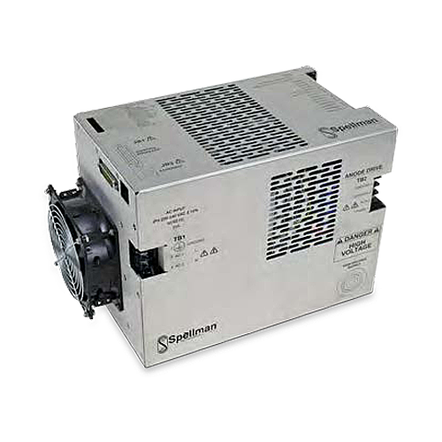
PMXシリーズ
- マンモグラフィー・アプリケーションのためのカスタム設計
- コンパクトな省スペース設計モジュラーフォーマット
- 立ち上がり・立ち下がり時間が短く、患者への不必要な放射線被爆を最小化
- デュアルスピードスターター、ブースト/ブレーキ性能
- RS-232およびオプションのイーサネットインターフェイス
*注: すべての仕様は予告なく変更される場合があります。最新版についてはこのデータシートの英語PDFをご覧ください。


50kV X線ジェネレーター
スペルマンのPMXは、FFDMとDBTを含むマンモグラフィー用に特別設計された高性能X線ジェネレーターです。2および3ポイント露光モードおよび前露光のあるスマートAECを備えています。
PMXは、5kW高周波X線ジェネレーターであり、デュアルフィラメント電源と、デュアルスピードX線管スターターと統合されています。 PMXの卓越した電力変換テクノロジーとインバーター設計により、安定かつ正確なX線管高電圧を高速の立ち上がり・立ち下がり時間で提供できます。
PMXのスムーズなシステム統合は、RS-232とオプションのイーサネットデジタルインターフェイス、ロード済みX線管パラメーター、簡単アクセスインターロックとI/O接続、そして内部ジェネレーター診断機能を使用して達成されます。オプションのGUIユーティリティソフトウェアも内部システム統合を支援するために提供可能です。
Specifications
(Ref. 128113-001 REV. C)
Input Voltage:
200-240Vac (±10%), single phase, 50Hz/60Hz
Input Current:
Minimum 35A service recommended for 5kW operation
External EMC Filter (Schaffner FN2070-36-08-36A) required to meet CE/EMC specifications – Not provided
Mains Contactor – Not provided
Customer is responsible for mains safety disconnection.
Output (Tube) Voltage
Output Voltage Range:
20kV to 49kV
Polarity:
Positive, grounded cathode X-Ray tube
Accuracy:
2% (measured per IEC60601-2-45)
Reproductibility:
<0.5%
Rise Time:
<1ms to within 98% of the programmed voltage
Fall Time:
<10ms with a max HV cable length of 8 feet (2.4 meters)
Ripple:
≤ 4% p-p
Output (Tube) Current/Power:
Output Current Range:
10mA to 200mA
Output Power:
5kW @ 0.1 second loading time,
300 Watts maximum average power
Accuracy:
< ±10% on exposure less than 10ms (measured per IEC60601-2-45)
Rise Time:
<1ms to within 95% of the programmed mA value
Fall Time:
<10ms with a maximum HV cable length of 8 feet (2.4 meters)
Exposure Time (Loading Time):
Maximum Single Exposure Time:
10 seconds
Shortest Single Exposure Time:
5ms
Loading time accuracy:
±3% +1ms (measured per IEC60601-2-45)
Maximum mAs:
600mAs
Exposure Timer:
5mS-10 seconds
Accuracy:
< ±10% (measured per IEC60601-2-45)
Reproductibility:
<0.5%
Filament Configuration:
DC filament drive: self corrected filament preheat settings with closed loop emission control and smart learning algorithm
Filament Output:
0-6 amps at a compliance of 5.5 volts, maximum.
Dual Speed Starter:
High speed (180Hz) and low speed (60Hz) can be configured via the serial interface.
Boost and Brake capability provided.
High Voltage Connector:
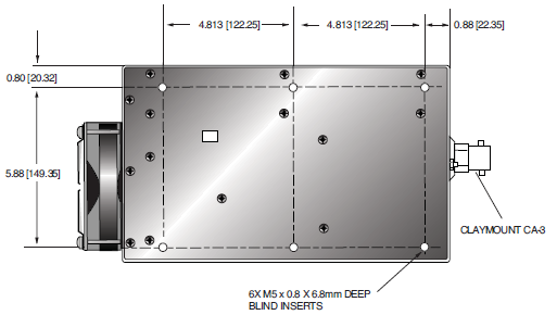
60kV, Claymount CA-3 type or equivalent
Communication Interface:
RS-232 standard, optional Ethernet
Grounding Point:
M5 ground stud provided on chassis
Environmental:
Temperature Range:
Operating: 10°C to 40°C
Storage: -40°C to 85°C
Humidity:
20% to 85% RH, non-condensing.
Cooling:
Internal fan
Dimensions:
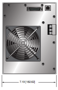
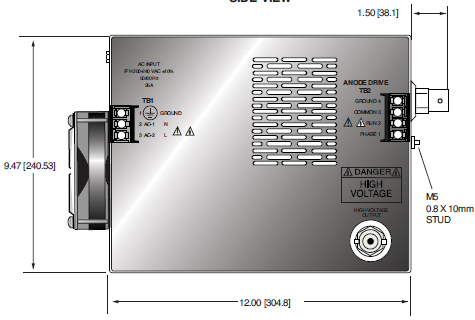
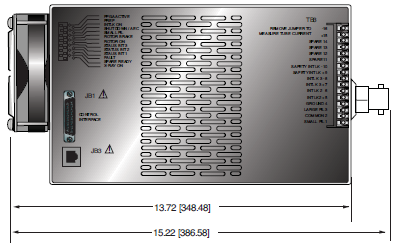
9.47. H X 7.19. W X 13.72. D (240.5mm x 182.6mm x 348.5mm)
Weight:
<23 pounds (10.5kg)
Regulatory Approvals:
Designed to meet EMC:IEC 60601-1-2. UL/CUL recognized file E242584. RoHS compliant.
Application Features:
- 2 point/3 point exposure modes
- AEC/Smart AEC exposure modes
- Dual Speed Starter
- X-Ray tube anode heat calculator
- Preloaded X-Ray tube parameters and expandable X-Ray tube library
TB2 ROTOR INTERFACE
| Pin | Signal | Parameters |
|---|---|---|
| TB2-1 | Phase | To tube auxiliary winding |
| TB2-2 | Run | To tube principle winding |
| TB2-3 | Com | To tube common winding |
| TB2-4 | Ground | To tube housing ground |
PMX STANDARD SYSTEM INTERFACE— JB1 25 PIN MALE D CONNECTOR
| Pin | Signal | Parameters |
|---|---|---|
| 1 | GND | Signal Ground |
| 2 | +5Vdc Out | +5Vdc, 100mA max. |
| 3 | RS-232 Tx Out | RS-232 Transmit |
| 4 | RS-232 Rx In | RS-232 Receive |
| 5 | PREP | User signal (Contact Closure) to alert the generatorthat exposure sequence will begin. Once this signalis active, exposure parameters are locked in andcannot be changed. The generator enables thestarter to to boost the rotor. Contact connection to pin 24. Closed = PREP, the filament is placed inpreheat mode |
| 6 | READY | Generator signal to user to indicate the rotor runs tospeed and the generator is ready for X-Ray exposureOpen Collector. Low/Active = Ready |
| 7 | ROTOR SHUTDOWN | User signal to brake the rotor drive |
| 8 | EXPOSURE | User signal (Contact Closure) to generator to generate X-Rays. Filament is boosted, and highvoltage is generated after the boost time. Contactconnection to pin 24. Closed = Exposure |
| 9 | X-Ray ON 75% Status | Transistor output to indicate X-Ray ON statussynchronized with 75% of kVP setting point. |
| 10 | X-Ray ON Status | Transistor output to indicate X-Ray ON statussynchronized with kV start up. |
| 11 | N/C | N/C |
| 12 | X-Ray SHUTDOWN/AEC | User signal to generator to rapidly turn HV OFFand ON during serial exposure sequence |
| 13 | RS-232 ISO Ground | Isolated ground from RS-232 transceiver IC |
| 14 | HVG FAULT Status | Generator signal indicating generator fault. Opencollector transistor output. Low/Active = Fault |
| 15 | Status Bit 1 | 3 bit status lines for up to 6 status messages. separate matrix descibing functionality. Open Collector. Low/Active = Message |
| 16 | Status Bit 2 | |
| 17 | Status Bit 3 | |
| 18 | N/C | N/C |
| 19 | N/C | N/C |
| 20 | kV Monitor | Signal from generator. 0-10V = 0-50kV. Zout = 1kΩ |
| 21 | Emission Monitor | Signal from generator. 0-10V = 0-200mA. Zout = 1kΩ |
| 22 | Filament Current Monitor | Signal from generator. 0-10V = 0-6A. Zout = 1kΩ |
| 23 | Program/Monitor Return | Ground for reference of program and monitor signals |
| 24 | +24Vdc Out | For connection to PREP and EXPOSURE control relay coils |
| 25 | SHIELD/GND | For connection of interface cable shield to generatorchassis ground |
TB3 TUBE AND INTERLOCK INTERFACE
| Pin | Signal | Parameters |
|---|---|---|
| TB3-1 | SMALL FIL | Connection to tube small filament |
| TB3-2 | COMMON | Connection to tube filament common |
| TB3-3 | LARGE FIL | Connection to large filament |
| TB3-4 | GROUND | Generator chassis for cable shield connection |
| TB3-5 | Interlock 2+ | Used if tube has separate thermostat switch. Open = OVER TEMP. (short terminals if not used) |
| TB3-6 | Interlock 2- | |
| TB3-7 | Interlock 3+ | Used if tube has cooling circulator flow switch. Open = NO FLOW. (short terminals if not used) |
| TB3-8 | Interlock 3- | |
| TB3-9 | Safety Interlock+ | User signal (Contact Closure) for safety interlocks such as door interlocks. Open turns HV OFF, or inhibits HV from being generated.Closed = OK 24Vdc @ <1A typical |
| TB3-10 | Safety Interlock- | |
| TB3-11 | Contactor Coil+ | Option for contactor coil control |
| TB3-12 | Contactor Coil- | |
| TB3-13 | Spare | N/C |
| TB3-14 | Spare | N/C |
| TB3-15 | Tube Current+ | Tube current flows out from this pin |
| TB3-16 | Tube Current- | Tube current flows into this pin |
Tables & Diagrams
DIMENSIONS: in.[mm]
FRONT VIEW
SIDE VIEW
TOP VIEW
BOTTOM VIEW

