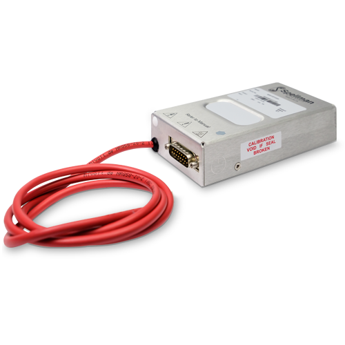
MPD Series
- Modulo de 10 Watts extremadamente compacto y de alto desempeño
- Multiples interfaces de control: Analogo diferencial, RS-232 y RS-485
- Monitores de Voltaje y Corriente
- Alta estabilidad, bajo coeficiente de temperatura
- Rizo y ruido ultra bajo, abajo de 1/f Banda
- GUI gratis para prueba y trabajo de desarrollo
- Control de funciones digitales: Múltiple operación de unidades, control de corriente, banderas de estado y función wobbler
Nota: Todas las especificaciones están sujetas a cambios sin previo aviso. Consulte la versión en ingles en PDF de esta hoja de datos para obtener la rversionn más actualizada.

Spellman MPD Series of High Voltage 10 Watt Modules
La serie MPD de Spellman es una familia de módulos de alto voltaje y alto rendimiento de 10 watts con voltajes de salida que van desde 1kV a 30kV.
La topología híbrida de Spellman de técnicas de conversión de energía lineal y de modo conmutado ofrece un ruido ultra bajo, excelente rendimiento de rizo y estabilidad, todo dentro de su huella compacta.
La serie MPD se puede controlar a través de interfaces analógicas o digitales, ambas proporcionadas a través de un conector estándar de tipo D de 15 pines.
En el modo analógico, la unidad cuenta con una entrada de amplificador diferencial para la señal de programación de voltaje para mejorar la inmunidad al ruido del sistema externo y abordar cualquier problema de compensación. En el modo digital, las interfaces RS-232 y RS-485 proporcionan características adicionales: control de corriente, indicadores de estado, operación de unidades múltiples (solo RS-485) y función wobbler.
La tecnología HV patentada de Spellman junto con los circuitos SMT dan como resultado un módulo ultracompacto y liviano, disponible como suministro positivo o negativo, que es ideal para aplicaciones OEM.
Aplicaciones típicas
- Espectrometría de masas
- Lentes electrostáticas
- Equipo de prueba automático
- Electroforesis capilar
- Haces de electrones e iones
- Detectores de placas de microcanal
- Impresión electrostática
- Centelladores
- Multiplicadores de electrones
- Electrohilado
- Portriles electrostáticos
- Tubos fotomultiplicadores
Especificaciones
(Ref. 128142-001 REV. F)
SPECIFICATIONS
Input Voltage:
+24 Vdc, ±2Vdc
Input Current:
≤1 amp maximum
Output Voltage:
7 models available from 1kV to 30kV
Output Polarity:
Positive or negative, specify at time of order
Power:
10 watts, maximum
Voltage Regulation:
Line: For a 1V line change 10ppm
Load: 0-100% load 10ppm
Current Limit:
110% of rated output current. In digital control mode, the current limit is settable from 0 to 110% of the rated output current.
Ripple:
See “drift, ripple and noise” table
Stability:
After one hour warm up period.
10ppm/hour
25ppm/8 hours
100ppm/1000 hours
Temperature Coefficient:
10ppm per degree C
Protection:
Arc and short circuit protected. Not designed to withstand continuous arcing. The unit monitors and reports faults through status flags (digital com). When a trip occurs, the output is disabled and the unit can be reset through enable, fault reset or power cycle.
Control Software:
A free GUI can be provided for customer testing and development work.
Main Features:
-Voltage control and enable inputs
-Voltage and current monitor outputs
-10V voltage reference output
Digital Features:
The following features are available when operating in digital control mode.
-Multiple units operation (RS-485 only)
-Current control
-Wobbler function: sine wave superimposed to voltage output (programmable amplitude 0-300V, period 0.1 to 2s)
Evironmental:
Operating: 0˚C to 50˚C
Storage: -35˚C to 85˚C
Environmental:
Temperature Range:
Operating: 0˚C to 50˚C
Storage: -35˚C to 85˚C
Humidity:
20% to 85% RH, non-condensing
Cooling:
Convection cooled
Dimensions:
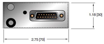
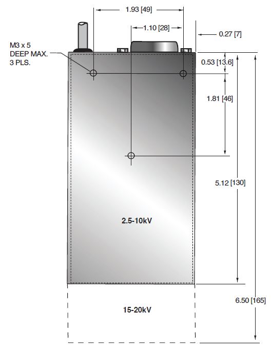
1kV-10kV: 1.18˝ H X 2.75˝ W X 5.12˝ D (30mm x 70mm x 130mm)
15kV-20kV: 1.18˝ H X 2.75˝ W X 6.50˝ D (30mm x 70mm x 165mm)
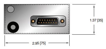
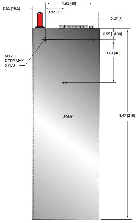
30kV-20kV: 1.38˝ H X 2.95˝ W X 8.46˝ D (35mm x 75mm x 215mm)
Weight:
1kV-10kV: 14.82 oz. (420g)
15kV-20kV: 22.93 oz. (650g)
30kV: 33.51 oz. (950g)
Interface Connector:
15 pin male D connector
Output Connector:
Captive 39.4˝ (1 meter) long un-terminated and shielded HV cable:
1kV to 20kV units: HRG58
30kV units: LEMO 130666
Regulatory Approvals:
Compliant to EEC Low Voltage Directive. UK Conformity Assessed. UL/CUL recognized, File E354595. RoHS Compliant.
Note: for 1kV and 30kV units approvals, please inquire.
MPD SELECTION TABLE
| Model | Output Voltage | Output Current |
|---|---|---|
| MPD1*10/24 | 1kV | 10mA |
| MPD2.5*10/24 | 2.5kV | 4.00 mA |
| MPD5*10/24 | 5kV | 2mA |
| MPD10*10/24 | 10kV | 1mA |
| MPD15*10/24 | 15kV | 0.66mA |
| MPD20*10/24 | 20kV | 0.5mA |
| MPD30*10/24 | 30kV | 0.33mA |
*Specify “P” for positive polarity or “N” for negative polarity. Custom units available.
MPD DRIFT, RIPPLE and NOISE
| Model | 3mHz-30mHz | 30mHz-3Hz | 3Hz-30Hz | 30Hz-300Hz | 300Hz-30kHz | 30kHz-3MHz |
|---|---|---|---|---|---|---|
| MPD1 | 7mV | 7mV | 7mV | 4mV | 4mV | 4mV |
| MPD2.5 | 10mV | 10mV |
10mV | 5mV | 5mV | 5mV |
| MPD5 | 10mV | 10mV | 10mV | 10mV | 10mV | 10mV |
| MPD10 | 20mV | 20mV | 20mV | 20mV | 20mV | 20mV |
| MPD15 | 30mV | 30mV | 30mV | 30mV | 30mV | 30mV |
| MPD20 | 40mV | 40mV | 40mV | 40mV | 40mV | 40mV |
| MPD30 | 60mV | 60mV | 60mV | 60mV | 60mV | 60mV |
MPD EXTERNAL INTERFACE—15 PIN MALE D CONNECTOR
| Pin | Signal | Parameters |
|---|---|---|
| 1 | Power Ground | Ground |
| 2 | +24Vdc Input | +24Vdc @ 1 amp maximum |
| 3 | Voltage Monitor Output | Voltage monitor 0-10Vdc for 0 to full scale output ±1% (wrt signal ground) Zout=10kΩ |
| 4 | Voltage Reference Output | 10Vdc @ 10mA maximum |
| 5 | Voltage Program Input | 0 to 10Vdc=0 to 100% rated output ±1%, Zin=10MΩ |
| 6 | Voltage Program Differential Amplifier Output |
0 to 10Vdc=0 to 100% rated output, Zout =10kΩ |
| 7 | Voltage Program Differential Amplifier Input—Positive |
0 to 10Vdc differential between pin 7 and pin 9 = 0 to 100% of rated output, diode clamped to ground, Zin =38kΩ |
| 8 | Current Monitor Output | Voltage monitor 0 to 10Vdc for 0 to full scale output ±1% (wrt signal ground) Zout=10kΩ |
| 9 | Voltage Program Differential Amplifier Input—Negative |
0 to 10Vdc differential between pin 7 and pin 9 = 0 to 100% of rated output, diode clamped to ground, Zin =38kΩ |
| 10 | Voltage Program Digital Output |
0 to 10Vdc = 0 to 100% rated output, Zout =10kΩ |
| 11 | Analog Signal Ground | Signal ground for control and monitoring |
| 12 | Enable Input | Low = Enable, TTL, CMOS, open collector compliant |
| 13 | Digital Mode | RS-232 or RS-485 configuration Low = RS-485, Open circuit = RS-232 |
| 14 | RS-232 TxD/RS-485 (-) | Transmit data (output) wrt pin 1 or RS-485 inverting |
| 15 | RS-232 RxD/RS-485 (+) | Receive data (input) wrt pin 1 or RS-485 non inverting |
Digital Control – Connect pin 5 to pin 10
Analog Control – Connect pin 5 to pin 6
Tablas y Diagramas
DIMENSIONS: in.[mm]
1kV-20kV
FRONT VIEW
BOTTOM VIEW
SIDE VIEW
30kV
FRONT VIEW
BOTTOM VIEW
SIDE VIEW
Frequently Asked Questions
What Is a Safe Level of High Voltage?
Where Can I Obtain Information on High Voltage Safety Practices?
What Kind of High Voltage Connector Do You Use on Your Supplies?
What Do You Mean That the Output Side of the High Voltage Cable on Most Standard Products Is “Unterminated”?
How Should I Ground Your Supply?
Why Is Arcing an Issue for a High Voltage Power Supply?

