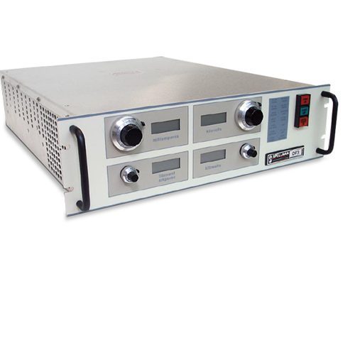
DF/FF Series
- Ideal for Common XRD & XRF X-Ray Tubes
- Designed for Common XRD & XRF X-Ray Tubes
- Compact Size, 5 1/4” (3U) High Chassis
- Solid Encapsulation Ensures Maintenance-Free Operation
- Auto Ramp of the HV Emission Current to Preset Values
- OEM Customization Available
*Note: All specifications are subject to change without notice. Please consult the English PDF version of this datasheet for the most up-to-date revision.

![]()
DF/FF Series 3-4kW Industrial X-Ray Generators
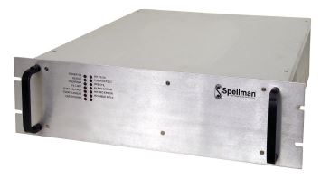
Spellman’s DF/FF Series of X-Ray Generators feature our new inverter design which incorporates IGBTs for power switching and provides new levels of reliability. In addition, re-engineering of the DF/FF’s internal filament power supply eliminates audio noise at normal operating levels by operating at a higher frequency. The DF/FF’s utilize a sine wave current source, produced by phase shifting series resonant circuits at switching frequencies greater than 20kHz to generate high voltage dc. This technique eliminates undesirable electromagnetic radiation normally associated with switching and power control regulators. The high efficiency of these units allows for air cooling in a 5 1/4” (3U) high chassis.
Typical applications:
- X-Ray Diffraction (XRD)
- X-Ray Fluorescence (XRF)
Specifications
(Ref. 128001-001 REV. T)
Input Voltage:
220Vac ±10%, 50 or 60 Hz, single phase (three phase optional).
Input Current:
3kW: 220Vac @ 29.5A, single phase
208Vac @ 12.8A/phase, three phase
4kW: 220Vac @ 39.3A, single phase
208Vac @ 17.0A/phase, three phase
Output Voltage:
DF3: 0 to 60kV negative polarity.
FF3: 0 to 60kV positive polarity.
Other output voltages are available.
Output Current:
DF3: 0 to 80mA.
FF3: 0 to 100mA. Other output currents are available.
Maximum Output Power:
3kW (4kW optional).
Output Voltage Regulation:
Load: 0.005% of rated output for full load change.
Line: 0.005% of rated output over specified input range.
Temperature Coefficient: 50 ppm/°C (20 ppm/°C optional).
Long Term Stability: 0.01%/8 hours.
Emission Current Regulation:
Load: 0.01% of rated output for a 10 to 60kV change.
Line: 0.005% of rated output over specified inputs.
Temperature Coefficient: 50 ppm/°C
Long Term Stability: 0.01%/8 hours.
Ripple:
0.03% rms <1kHz, 0.75% rms above 1kHz.
Environmental:
Temperature Range:
Operating: 0°C to 40°C
Storage: -20°C to 85°C
Humidity:
10% to 90%, non-condensing.
Filament Voltage:
DF: 12Vac
FF: 12Vdc
Filament Current:
5A (up to 12A max available).
Dimensions:
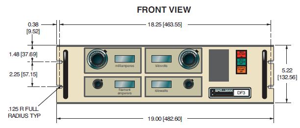
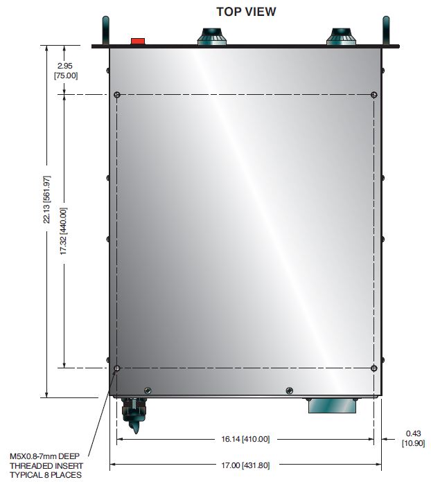
51/4”(3U) H x 19“ W x 22” D (13.3cm x 48.3cm x 55.9cm).
Weight:
90 lbs (40kg).
Regulatory Approvals:
Compliant to EEC EMC Directive. Compliant to EEC Low Voltage Directive.
ADDITIONAL FEATURES
Water Flow Switch:
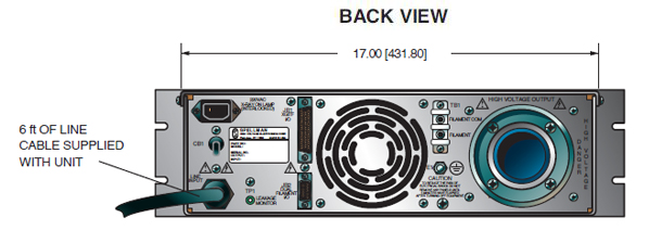
A 24Vdc signal is available on the rear panel to turn on the cooling water to the X-ray tube. This signal can be enabled either when control power is on or when the high voltage is turned on. (Customer must specify).
Fail Safe Interlock:
A 24Vdc signal is available on the rear panel to energize an external X-ray on lamp. This signal is energized when the high voltage is turned on. High voltage will not enable if this circuit is open. (A 220Vac signal is optional).
Preheat and Ramp:
Automatic preheat and ramp control circuits are provided which ramp the kV and mA slowly to set levels. kV ramps in approximately 10 seconds while mA ramps in approximately 20 seconds.
Output Connector:
75kV, 3 conductor Federal Standard X-ray connector. -60kV is connected to terminal “C”. Terminals “S” and “L” are jumped together. The filament output is connected between terminals “C” and “S”. Other configurations are optional. (On the FF3, all output connections S, L, & C are connected together).
Remote Signal Connector:
Remote interface is available via a 50 pin mini D connector. Extensive remote programming and monitoring is provided.
OPTIONS
RS232 - RS232 Interface
220FSI - 220Vac Fail Safe Interlock
208-3P - 208Vac Three Phase Input
Electronic Component (Power Source)
DF/FF series is intended for installation as a component of a system. It is designed to meet CE standards, with conditions of acceptance often being: customer provided enclosure mounting, EMC filtering, and appropriate protection, and isolation devices. The DF/FF series is not intended to be operated by end users as a stand-alone device. The DF/FF series power supply can only be fully assessed when installed within a system, and as a component part within that system.
JB1 MINI D CONNECTOR 50 PIN
| Pin | Signal |
|---|---|
| 1 | +5Vdc (or connect to pin-11) |
| 2 | Control Power On |
| 3 | Intlk |
| 4 | X-Ray On |
| 5 | X-Ray Off |
| 6 | Spare |
| 7 | Spare |
| 8 | Reset |
| 9 | Rmt/Lcl |
| 10 | 24V Switched |
| 11 | +5Vcch |
| 12 | X-ray On Status |
| 13 | Overvoltage |
| 14 | kV Min |
| 15 | Overpower |
| 16 | Filament Current Limit |
| 17 | mA Current Limit |
| 18 | LCL Status |
| 19 | Power Supply Fault |
| 20 | Gnd |
| 21 | Spare |
| 22 | (DF) Remote X-ray On |
| 23 | (DF) Remote X-ray On Ret |
| 24 | Spare |
| 25 | Gnd |
| 26 | kV Ref |
| 27 | kV Com |
| 28 | mA Ref |
| 29 | mA Com |
| 30 | Spare |
| 31 | Spare |
| 32 | Spare |
| 33 | Pwr. Limit (OL Ref) |
| 34 | Pwr. Limit Com (OL Com) |
| 35 | Filament Current Limit |
| 36 | Filament Current Limit Com |
| 37 | Spare |
| 38 | kV Monitor |
| 39 | mA Monitor |
| 40 | Spare |
| 41 | Spare |
| 42 | kV Ref Mon |
| 43 | mA Ref Mon |
| 44 | Spare |
| 45 | Spare |
| 46 | Filament Monitor |
| 47 | Mon Common |
| 48 | Spare |
| 49 | Gnd |
| 50 | Spare |
Tables & Diagrams
DIMENSIONS: in.[mm]
Cost reduced version for OEM quantities available, contact Sales.
Frequently Asked Questions
Application Notes AN-12 – The Benefit of Using a Current Source to Power X-Ray Tube Filament Circuits
Application Notes AN-14 – The Limits of Front Panel Digital Meters
Application Notes AN-01 – Fundamentals of X-Ray Generator – X-Ray Tube Optimization

