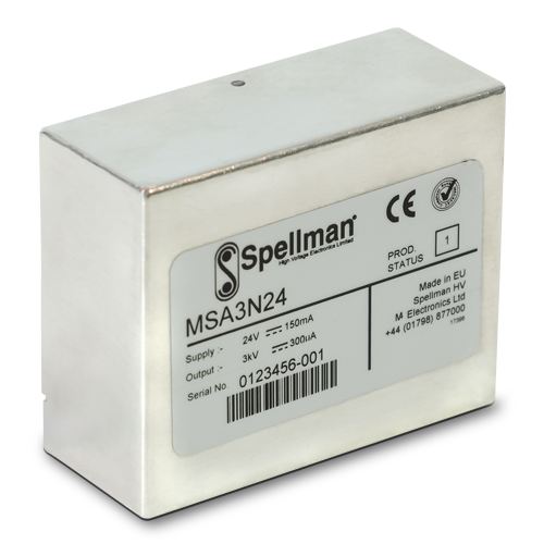
MSA Серия
- Компактный высокоэффективный модуль
- Программирование выходного напряжения
- Выходная мощность 0,9 Вт
- Контроль напряжения
- Защита от дугового разряда и короткого замыкания
*Примечание: все характеристики могут быть изменены без предварительного уведомления. Наиболее актуальная версия настоящей спецификации доступна на английском языке в формате PDF.

MSA
Модуль серии MSA представляет собой компактный высоковольтный блок питания, монтируемый на печатную плату (PCB), рабочий диапазон выходного напряжения от 1 кВ до 3 кВ с положительной или отрицательной полярностью. Серия MSA оснащена функцией программирования выходного напряжения (сигнал 0-10 В постоянного тока), что соответствует уровню 0-100% от номинального выходного напряжения. Предусмотрен контроль выходного напряжения, уровень от 0 до 10 В постоянного тока соответствует уровню 0-100% от номинального выходного напряжения. Дополнительно сигнал состояния и сигнал разрешения обеспечивают простое управление источником питания. Все устройства имеют встроенную защиту от неисправностей.
Серия MSA предназначена для широкого применения в тех случаях, когда требуется компактный высокопроизводительный источник питания, монтируемый на печатную плату, например, для управления электронным умножителем в масс-спектрометре. Благодаря алюминиевому корпусу обеспечивается снижение уровня шума, создаваемого устройством./p>
Стандартные области применения:
- фотоэлектронные, умножители,
- электронные умножители,
- масс-спектрометрия,
- электростатические линзы,
- ядерное приборостроение.
Технические характеристики
(Ref. 128018-001 REV. D)
SPECIFICATIONS
Input Voltage:
+24 Vdc, ±2Vdc
Input Current:
150mA maximum input current
30mA pk-pk maximum input current ripple
Output Polarity:
Positive or negative, specify at time of order
Output Power:
0.9 watts, maximum
Output Voltage Accuracy:
±1%
Voltage Regulation:
Line: 21.6Vdc to 26.4Vdc, ±0.02%
Load: 0-100% rated load, ±0.02%
Stability: 50ppm/8hrs after one hour warm up period
Temperature Coefficient:
25ppm per degree C
Settling Time: After Power On or Enable
100 milliseconds, typical
When power is removed the unit will decay to <±60 volts within 2 seconds
Protection:
Arc and short circuit protected.
Not designed to withstand continuous arcing
Environmental:
Temperature Range:
Operating: 0˚C to 60˚C
Storage: -20˚C to 70˚C
Humidity:
95% RH, non-condensing
Cooling: Convection cooled
Dimensions:
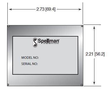
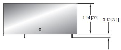
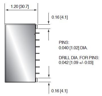
2.73˝ L x 2.21˝ W x 1.21˝ D (69.4mm x 56.2mm x 30.7mm)
Weight:
7.0 oz. (200g)
Regulatory Approvals:
Designed to meet EN 61010-1, UL 61010A-1 and CAN/CSA-22.2 No. 61010.1 As the unit is intended for incorporation into end users equipment it will not be tested as a standalone unit to meet the EMC directive. The user will need to follow sensible EMC precautions in using the unit. The unit is compliant with the EU RoHS directive
MSA SELECTION TABLE
| Model | Output Voltage | Output Current | Ripple (Vpp) |
|---|---|---|---|
| MSA1*24 | 0-1kV | 0-900μA | 30mV |
| MSA2*24 | 0-2kV | 0-450μA | 40mV |
| MSA3*24 | 0-3kV | 0-300μA | 50mV |
1) Replace the * with “P” for positive output polarity and “N” for negative output polarity.
2) The ripple figure includes random non switch related noise, noise related to the oscillator, switching and feedback control circuitry and noise associated with the rectified primary switching frequency.
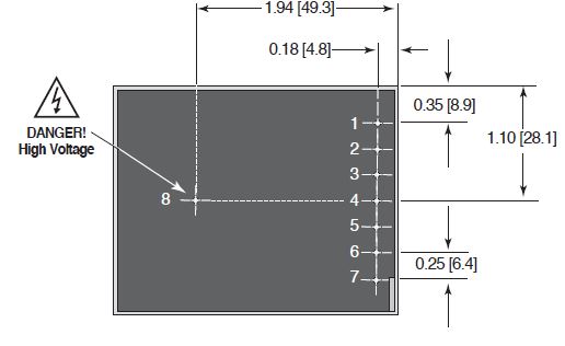
LOW VOLTAGE SIGNAL PINS FOR POWER AND CONTROL
| PIN | SIGNAL | LEVEL | SIGNAL PARAMETERS |
|---|---|---|---|
| 1 | Enable | TTL | Enable = Low (≤1.2V). Disable = High (≥2.4V), when Enable pin is NC, 10kΩ pull up to +5V ±10% |
| 2 | Status | 0V/5V | OK = 11kΩ pull up to +5.1V ±10%. Fault = ≤0.1V, Zout = 1kΩ |
| 3 | Voltage Program | 0-10V | 0 to +10Vdc = 0 to 100% rated output voltage, Accuracy ≈ ±1%. Zin = 10kΩ |
| 4 | Voltage Monitor | 0-10V | 0 to +10Vdc = 0 to 100% rated output voltage, Accuracy = ±2%. Zout = 20kΩ |
| 5 | Input Voltage | 24Vdc | Power Input |
| 6* | Signal Ground | 0V | Ground reference for control and monitoring signals |
| 7* | Power Ground | 0V | Power Return |
To reset the unit after a fault condition, Pin1 (Enable) must be set high for at least 10 seconds
* pins 6 & 7 are linked internally
HIGH VOLTAGE CONNECTION DETAIL
| PIN | SIGNAL | SIGNAL PARAMETERS |
|---|---|---|
| 8 | High Voltage Output | 0-100% Rated Output. !!Danger: High Voltage!! |
Таблицы и диаграммы
DIMENSIONS: in.[mm]
TOP VIEW
FRONT VIEW
BOTTOM VIEW
SIDE VIEW
Frequently Asked Questions
What Is a Safe Level of High Voltage?
Where Can I Obtain Information on High Voltage Safety Practices?
How Should I Ground Your Supply?
Why Is Arcing an Issue for a High Voltage Power Supply?

