CT GENERATOR
* Ask about our subsystem capabilities
- 32, 42 and 50kW all in the same footprint and volume
- Utilizes Spellman’s own SPI interface (compatible with other Spellman CT generators)
- 16/32 slice with 0.5 second rotation
- Supports Spellman’s add on Grid Box Option
- Integrated anode drive (supporting ball or liquid metal bearings)
*Note: All specifications are subject to change without notice. Please consult the English PDF version of this datasheet for the most up-to-date revision.
Spellman CCT Series | CT X-Ray Generators
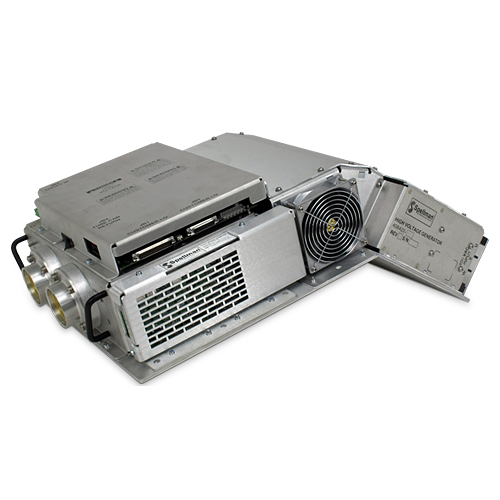
Spellman High Voltage has been designing, manufacturing and providing CT generators for OEM customers for over three decades. We have unrivaled experience being the first provider of a CT generator used in a commercially available continuous rotating CT scanner in 1985. Since then Spellman has enhanced performance and developed new CT generators year after year, setting the standard for CT generator technology.
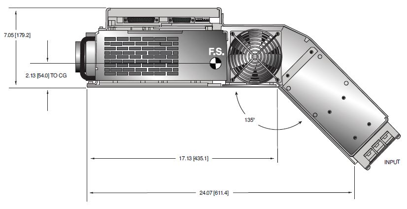
Spellman’s CCT series of CT generators provide a unique combination of performance and price. Ideally suited for the economy 16 slice CT scanner, this generator has the ability to be scaled from 32kW to 50kW. Its compact size and unique bend makes it suitable for small footprint gantry designs. Designed to easily pair with many off the shelf CT tubes.
사양
(Ref. 128125-001 REV. A)
OPTIONS
DG: Deflection Grid
CG: Cutoff Grid
SPECIFICATIONS
Input Voltage:
Main: 400Vac, three phase, +15%/-20%, 50/60Hz
Auxiliary: 220/230Vac, single phase, +15%/-10%, 50/60Hz
Output Voltage:
Range: 60kV to 140kV (bipolar, 30kV to 70KV)
Accuracy: ±0.5% of setting
Output Current:
Range: 10mA to 420mA, 50kW maximum.
10mA to 420mA, 50kW maximum.
10mA to 420mA, 50kW maximum.
Filament Output:
Auto reversible via front panel switch
Output Current:
Type: Two filament outputs, large and small
Voltage/Current: 15Vac (30kHz-40kHz) @ 0-6A maximum, referenced to cathode output
Power:
Maximum mA: 420mA, 50kW maximumMaximum kV: 140kV, 50kW maximum
Peak: 50kW
Maximum mA: 350mA, 42kW maximum
Maximum kV: 140kV, 42kW maximum
Peak: 42kW
Maximum mA: 275mA, 32kW maximum
Maximum kV: 140kV, 32kW maximum
Peak: 32kW
Gantry Rotation:
0.5 seconds
Starter:
Type: Dual Speed Starter
Compatibility: All industry standard X-Ray tubes
GRID SPECIFICATIONS
Deflection Grid: The deflection grid (also called the Flying Focal Spot) allows for dynamic movement of the focal spot providing double X sampling which increases effective resolution while decreasing unwanted artifacts.
Type: Deflection grid, single box assembly
Input Power: 24Vdc, ±10% @ 4.2A maximum, negative input ties to chassis ground internally
Connectors:
High Voltage Input: 3 pin 75kV Federal Standard (Cathode, Large, Small)
High Voltage Output: 4 pin 75kV CA7 (Cathode, Large, G1, G2)
Number of Grids: 2 grids, switching out of phase Bandwidth: DC to 5kHz
Output Voltage: 0V to -4KV, from grid to cathode. User input will command the bi-level grids to switch between adjustable voltages, VLOW and VHI. The two grids switch out of phase: If G1 is at VLOW, G2 will be at VHI and vice versa. The VLOW and VHI levels for G1 and G2 are independently adjustable from 0 to -4KV but VLOW range is constrained by: |VLOW | ≤ | VHI |
Cutoff Grid:
A cutoff grid truncates the high voltage at the end of the X-Ray exposure, reducing patient radiation dosing that does not contribute to the imaging process.
Type: Cutoff grid, single box assembly Input Power: 24Vdc, ±10% @ 0.75A maximum, negative input ties to chassis ground internally
Connectors:
High Voltage Input:
3 pin 75kV Federal Standard (Cathode, Large, Small)
High Voltage Output:
4 pin 75kV CA7 (Cathode, Large, G1, G2)
Number of Grids:
One, switched between “Zero” (0V≥Vg-c ZERO ≥ -10V) and “Cutoff” (Vg-c CUTOFF = -4kV±10% @ steady state)
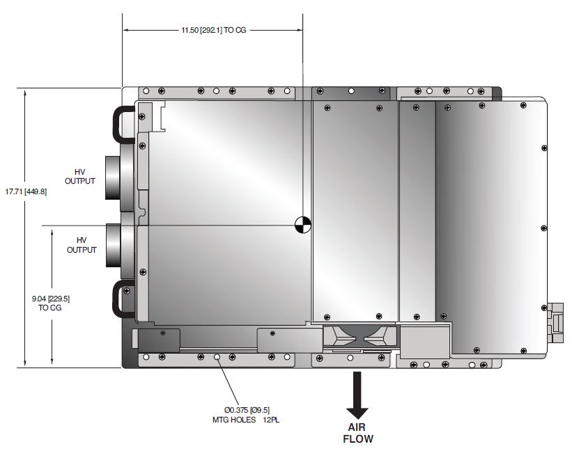
CCT X-RAY GENERATOR
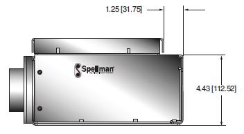
DIMENSIONS: in.[mm]
TOP VIEW
SIDE VIEW
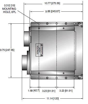
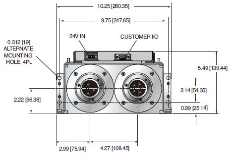
DEFLECTION / CUTOFF GRID
DIMENSIONS: in.[mm]
TOP VIEW
SIDE VIEW
FRONT VIEW
테이블 및 다이어그램
| How to Order: | |
|---|---|
| 32kW maximum: | PART NO.: CCT70PN32 |
| 42kW maximum: | PART NO.: CCT70PN42 |
| 50kW maximum: | PART NO.: CCT70PN50 |
Consult sales for grid options
Frequently Asked Questions
Application Notes AN-12 – The Benefit of Using a Current Source to Power X-Ray Tube Filament Circuits
Application Notes AN-01 – Fundamentals of X-Ray Generator – X-Ray Tube Optimization

