MPSシリーズ
- 電圧プログラム用差動入力
- オプションのRS-232/RS-485コントロール
- 電圧、電流モニターとコントロール
- 高安定度、超低リップルとノイズ
- CEマーク、UL61010A-1承認
*注: すべての仕様は予告なく変更される場合があります。最新版についてはこのデータシートの英語PDFをご覧ください。
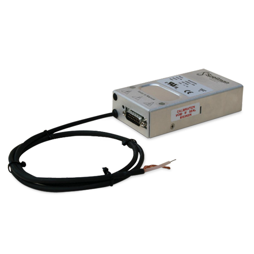
10W DC高圧電源
MPSシリーズは、10Wで1kV〜30kVの直流電圧を供給する高圧モジュールです。
MPSシリーズは、スペルマン社のリニアとスイッチ・モード電 力変換技術の複合トポロジを駆使して設計された高性能製品で、 高効率を備える一方でノイズを低減しコンパクトなフットプリン トにより優れたリップルおよび高安定特性を提供します。また、 電圧プログラミング信号用差動アンプ入力を特徴とし、外部シス テムのノイズイミュニティを改善し、オフセットでの課題を処理 します。これに代わる方法として、出力電圧を内部ポテンショメー タでプリセットすることも可能です。
RS-232またはRS-485デジタルインターフェースもオプションとして利用できます。標準のアナログとオプションのデジタルコントロールは、どちらも15ピンのDタイプコネクタ経由で利用可能です。
SMT回路と組み合わせたスペルマン独自の高圧テクノロジーにより、OEMアプリケーションに最適な、正極または負極の電源として利用可能な、超コンパクトで軽量なモジュールが実現しました。
用途
- フォトマルチプライヤ
- マイクロ・チャネル・プレート検知器
- 電子マルチプライヤ検知器
- シンチレータ
- 質量分析
- 電子およびイオンビーム 静電レンズ 核計測 静電印刷
Specifications
(Ref. 128033-001 REV. T)
Input Voltage:
+24 Vdc, ±2Vdc
Input Current:
≤ 1 amp maximum
Output Voltage:
9 models available from 1kV to 30kV
Output Polarity:
Positive or negative, specify at time of order
Power:
10 watts, maximum
Voltage Regulation:
Line: ≤ 0.001% of rated output voltage over specified input voltage
Load: ≤ 0.001% of rated output voltage for full load change
Current Regulation (VCC Option):
Line: ≤ 0.01% for 1V input voltage change under any load conditions
Load: ≤ 0.01% for full load to short circuit
Ripple:
See “model selection” table
Stability:
≤ 0.007% per hour, 0.02% per 8 hours after 1.0 hour warm up period.
≤ 0.05% per 1000 hours after 1.0 hour warm up period (HS option)
Temperature Coefficient:
≤ 25ppm per degree C
≤ 10ppm per degree C (HS option)
Environmental:
Temperature Range:
Operating: 0°C to 50°C
Storage: -35°C to 85°C
Humidity:
20% to 85% RH, non-condensing
Cooling:
Convection cooled
Dimensions:
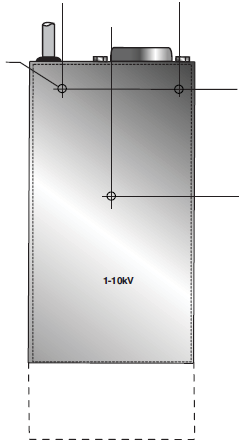
1-10kV: 1.18. H X 2.75. W X 5.12. D (30mm x 70mm x 130mm)
15-20kV: 1.18. H X 2.75. W X 6.49. D (30mm x 70mm x 165mm)
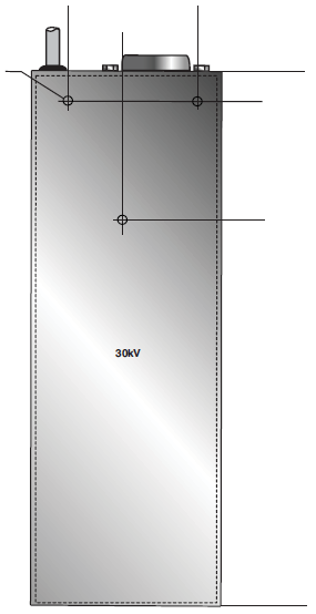
30kV: 1.37. H X 2.95. W X 8.47. D (65mm x 75mm x 215mm)
Weight:
1-3kV: 9.88 oz. (280g)
5-10kV: 14.82 oz. (420g)
15-20kV: 22.92 oz. (650g)
30kV: 35.51 oz. (950g)
Interface Connector:
15 pin male D connector
Output Connectors:
A captive 39.4˝ (1 meter) long shielded HV cable is provided
Regulatory Approvals:
UL recognized component (RC), File E354595. Compliant to EC/UL 61010-1 Safety requirements for electrical equipment for measurement, control and laboratory use; CAN/CSA-C22.2 No.61010-1. CE marked to EN 61010-1. UKAS marked to BS EN 61010-1. RoHS compliant.
As the unit is designed for incorporation within the users system it is not tested against any specific EMC standards. The user will need to take sensible EMC precautions when designing the unit in and verify the overall system EMCperformance against any relevant standards.
Options:
VCC - Variable Current Control
HS - High Stability
DCC 2 - RS-232
DCC 4 - RS-485
Note: It is not possible to supply the unit with both full HS and DCC options
MPS ANALOG INTERFACE— 15 PIN D CONNECTOR (NON-DCC UNITS)
| Pin | Signal | Signal Parameters |
|---|---|---|
| 1 | Power/Signal Ground | Ground (also used as analog signal ground on 1kV to 10kV units) |
| 2 | +24Vdc Input | +24Vdc @ 1 amp maximum |
| 3 | Voltage Monitor Output | 0 to 10Vdc=0 to 100% Rated Output ±2%, Zout =10kΩ |
| 4 | Local Programming Potentiometer Wiper Output | Potentiometer connected to +10Vdc (accuracy: 0.2%) and ground, 0 to 10Vdc adjustable wiper output provided |
| 5 | Voltage Program Input | 0 to 10Vdc=0 to 100% Rated Output ±2%, Zin=10MΩ |
| 6 | Voltage Program Differential Amplifier Output | 0 to 10Vdc=0 to 100% Rated Output, Zout =10kΩ |
| 7 | Voltage Program Differential Amplifier Input—Positive | 0 to 10Vdc differential between pin 7 and pin 9 = 0 to 100% of rated output, diode clamped to ground, Zin =38kΩ |
| 8 | Current Monitor Output | 0 to 10Vdc = 0 to 100% Rated Output ±2%, Zout =10kΩ |
| 9 | Voltage Program Differential Amplifier Input—Negative | 0 to 10Vdc differential between pin 7 and pin 9 = 0 to 100% of Rated Output, diode clamped to ground, Zin =38kΩ |
| 10 | No Connection | No Connection |
| 11 | Current Program Input | Standard: Internally connected to provide 110% fixed current limit VCC Option: 0 to 10Vdc=0 to 100% Rated Output ±2%, Zin=1MΩ |
| 12 | Enable Input | Low = Enable, TTL, CMOS, Open Collector Compliant |
| 13 | Internal Connection | No Connection |
| 14 | Vref (/HS unit only) | +10V ultra high stability reference output. Accuracy: 0.05%, temperature coeff. <5ppm/°C On standard units the reference voltage is available on pin 4 |
| 15 | Analog Signal Ground (15kV to 20kV units) | Analog Signal Ground (No connection for (1kV to 10kV units) |
MPS DIGITAL INTERFACE— 15 PIN D CONNECTOR (DCC UNITS)
| Pin | Signal | Signal Parameters |
|---|---|---|
| 1 | Power/Signal Ground | Ground |
| 2 | +24Vdc Input | +24Vdc @ 1 amp maximum |
| 3 | No Connection | No Connection |
| 4 | Local Programming Potentiometer Wiper Output | Potentiometer connected to +10Vdc and Ground, 0 to 10Vdc adjustable wiper output provided |
| 5 | No Connection | No Connection |
| 6 | No Connection | No Connection |
| 7 | No Connection | No Connection |
| 8 | No Connection | No Connection |
| 9 | No Connection | No Connection |
| 10 | No Connection | No Connection |
| 11 | No Connection | No Connection |
| 12 | Enable Input | Low = Enable, TTL, CMOS, open collector compliant |
| 13 | No Connection | No Connection |
| 14 | TxD | Transmit data (output) with respect to ground (pin 1) |
| 15 | RxD | Receive data (input) with respect to ground (pin 1) |
Notes: 1.) The DCC option operated via a simple ASCII protocol. Contact us for more information.
2.) The HS and DCC option cannot be offered together
MPS SELECTION TABLE
| Model | Output Voltage | Output Current | Ripple (Vpp) |
|---|---|---|---|
| MPS1*10/24 | 1kV | 10mA | <10mV |
| MPS2*10/24 | 2kV | 5.00 mA | <20mV |
| MPS2.5*10/24 | 2.5kV | 4.00 mA | <25mV |
| MPS3*10/24 | 3kV | 3.3mA | <25mV |
| MPS5*10/24 | 5kV | 2mA | <30mV |
| MPS10*10/24 | 10kV | 1mA | <50mV |
| MPS15*10/24 | 15kV | 0.66mA | <100mV |
| MPS20*10/24 | 20kV | 0.5mA | <150mV |
| MPS30*10/24 | 30kV | 0.33mA | <250mV |
*Specify “P” for positive polarity or “N” for negative polarity. Custom units available.
| How To Order: | |||
|---|---|---|---|
| MPSXX*10/24/YYY where: XX is the Output voltage (see selection table) * is the polarity: P for positive / N for negative YYY is the option: VCC / HS / DCC2 / DCC4 |
Tables & Diagrams
DIMENSIONS: in.[mm]
1-20kV
FRONT VIEW

BOTTOM VIEW
SIDE VIEW
30kV
FRONT VIEW
BOTTOM VIEW
SIDE VIEW


