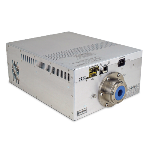
DXM100シリーズ
- 出力100kV @最高1200W
- 小型軽量モジュール式ユニット
- ユニバーサル入力、力率改善
- USB、イーサネット、RS-232 標準インターフェイス
- User Programmable Ramping and Arc Detect Feature
- CE準拠
*注: すべての仕様は予告なく変更される場合があります。最新版についてはこのデータシートの英語PDF版をご覧ください。

1200W 産業用X線ジェネレーター
DXMシリーズX線発生モジュールは、OEMアプリケーション 用に設計されており、1200Wで100kV迄対応します。ユニバー サル入力、小型パッケージ・サイズ、3種の標準デジタル・イン ターフェースの選択で、DXM100製品をお客様のX線分析装置 へ容易に統合することが可能になります。
DSPベースのエミッション電流制御回路で、際立つ安定性と ともに優れたエミッション電流のレギュレーションを提供します。
用途
- NDT分析
- 結晶検査
- メッキ計測
- ダイアモンド検査
- ミネラル分析
- 食品/製品検査
Specifications
(Ref. 128107-001 REV. J)
Input Voltage:
Power factor corrected input, ≥ 0.98 180-264Vac, 47-63Hz, 8.25A maximum
Output Voltage:
100kV, maximum
Output Polarity:
Negative-for floating filament X-Ray tubes
Output Current:
12mA maximum
Output Power:
1200 Watts maximum
Output Voltage Regulation:
≤ 0.01% of rated output voltage over specified input voltage range
≤ 0.01% of rated output voltage for a full load change
Emission Current Regulation:
≤ 0.01% of rated output current over specified input voltage range
≤ 0.01% of rated output current for a change from 30% to 100% of rated output voltage
Filament is disabled when kV is <30% of full scale output
Ripple:
≤ 1%rms at >20 kHz, 0.1%rms below 20 kHz
Stability:
≤ 25ppm/hr after a 2 hour warm up
Temperature Coefficient:
≤ 50ppm per degree C
Environmental:
Temperature Range:
Operating: 0°C to 40°C
Storage: -40°C to 85°C
Humidity:
20% to 85% RH, non-condensing.
Filament Configuration:
Closed loop emission control regulates filament setting
to provide desired X-Ray tube emission current.
Output: 5.0 amps at a compliance of 10.0 volts, maximum. The filament loop is disabled when the kV output is less than 30% of full scale output to protect the X-Ray tube. Other filament levels available on special order.
Control Interface:
Local Interface:
Potentiometers are provided to adjust filament limit and preheat levels
Remote Interface:
USB, Ethernet and RS-232 are standard. All digital monitors have an accuracy specification of 2%
Control Software:
A Windows graphical user interface example is provided
High Voltage Enable:
A hardware based, dry contact closure will enable the power supply into the high voltage on mode
Monitor Signals:
Voltage and current monitor signals are scaled 0-10Vdc equals 0-100% of full scale, accuracy is 1%
Over Power Fault:
The maximum power the unit can supply can be programmed (0-1200 watts) via the digital interface, this setting will be stored in memory. An over power fault will occur if the output power is ≥ 105% of the set point value. When an over power fault occurs the high voltage output will be disabled and the Over Power Fault indictor will be activated on the GUI/Applet. Additionally both the UV and OV fault LED’s on the DXM100 will be illuminated.
Cooling:
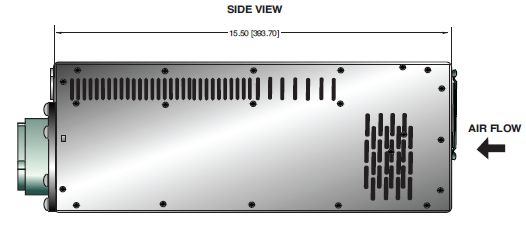
Forced air
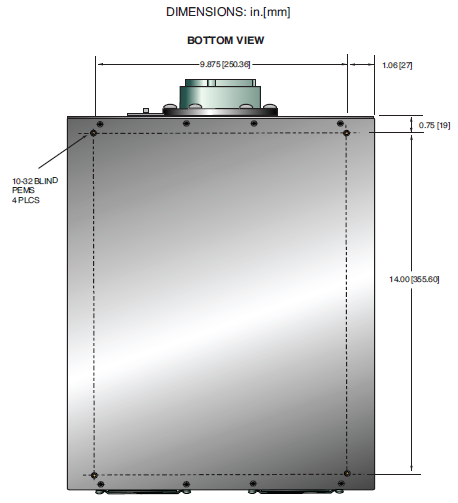
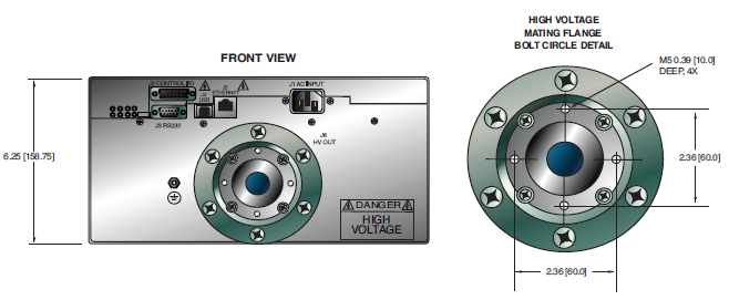
Dimensions:
6.25. H X 12. W X 15.5. D (158.75mm x 304.79mm x 393.7mm)
Weight:
43 pounds (19.5kg)
Input Line Connector:
IEC320 with EMI filter, 6´ (1.83 meter) cord set provided
Output Connector:
CA10 (R10). See table for pin out information
Regulatory Approvals:
Compliant to EEC EMC Directive. Compliant to EEC Low Voltage Directive. UL/CUL recognized, File E227588. RoHS Compliant.
DXM100 ANALOG INTERFACE—J2 15 PIN MALE D CONNECTOR
| Pin | Signal | Signal Parameters |
|---|---|---|
| 1 | Power Supply Fault | Open Collector, 35V @ 10mA Maximum |
| 2 | Current Program In | 0 to 10V=0 to 100% Rated Output, Zin=10MΩ |
| 3 | Voltage Program In | 0 to 10V=0 to 100% Rated Output, Zin=10MΩ |
| 4 | Filament Limit Input | 0 to 10V=0 to 100% Rated Output, Zin=10MΩ |
| 5 | Local Filament Limit | Multi-turn front panel potentiometer |
| 6 | Filament Preheat Input | 0 to 10V=0 to 100% Rated Output, Zin=10MΩ |
| 7 | Local Filament Preheat | Multi-turn front panel potentiometer |
| 8 | Voltage Monitor | 0 to 10V=0 to 100% Rated Output, Zout =4.99k, 1% |
| 9 | Signal Ground | Ground |
| 10 | Current Monitor | 0 to 10V=0 to 100% Rated Output, Zout =4.99k, 1% |
| 11 | X-ray Enable Input | Connect to Pin 12 to HV Enable Supply |
| 12 | X-ray Enable Output | +15V @ Open, ≤15mA @ Closed |
| 13 | Filament Monitor | 1 Volt=1 Amp, Zout=10kΩ |
| 14 | X-ray On Output Signal | Open Collector, 35V @10mA Maximum |
| 15 | Spare | NC |
RS-232 DIGITAL INTERFACE—J3 9 PIN FEMALE D CONNECTOR
| Pin | Signal | Signal Parameters |
|---|---|---|
| 1 | NC | No Connection |
| 2 | TX out | Transmit Data |
| 3 | RX in | Receive Data |
| 4 | NC | No Connection |
| 5 | SGND | Ground |
| 6 | NC | No Connection |
| 7 | NC | No Connection |
| 8 | NC | No Connection |
| 9 | NC | No Connection |
USB DIGITAL INTERFACE—J4 4 PIN USB "B" CONNECTOR
| Pin | Signal | Signal Parameters |
|---|---|---|
| 1 | VBUS | +5 Vdc |
| 2 | D- | Data - |
| 3 | D+ | Data + |
| 4 | GND | Ground |
ETHERNET DIGITAL INTERFACE—J5 8 PIN RJ45 CONNECTOR
| Pin | Signal | Signal Parameters |
|---|---|---|
| 1 | TX+ | Transmit Data + |
| 2 | TX- | Transmit Data - |
| 3 | RX+ | Receive Data + |
| 4 | NC | No Connection |
| 5 | NC | No Connection |
| 6 | RX- | Receive Data - |
| 7 | NC | No Connection |
| 8 | NC | No Connection |
J6 CA10 (R10) HV CONNECTOR
| Pin | Output Connection |
|---|---|
| C (common) | High Voltage Output |
| S (small) | High Voltage Output |
| L (large) | Filament Output |
Note: No high voltage cable is provided
Tables & Diagrams
DIMENSIONS: in.[mm]
BOTTOM VIEW
FRONT VIEW
SIDE VIEW
Note: All specifications are subject to change without notice. Please consult the PDF version of this datasheet for the most up-to-date revision.


